A point for Ingatestone
Tom Cunnington
7th May 2016
4 minutes
The track plan for Ingatestone is relatively simple, at least on the scenic part. However there are two points required and the requirement was for a “B7”. Here’s a quick guide to how it was built – you can try yourself at one of our Track Building skills transfer day.
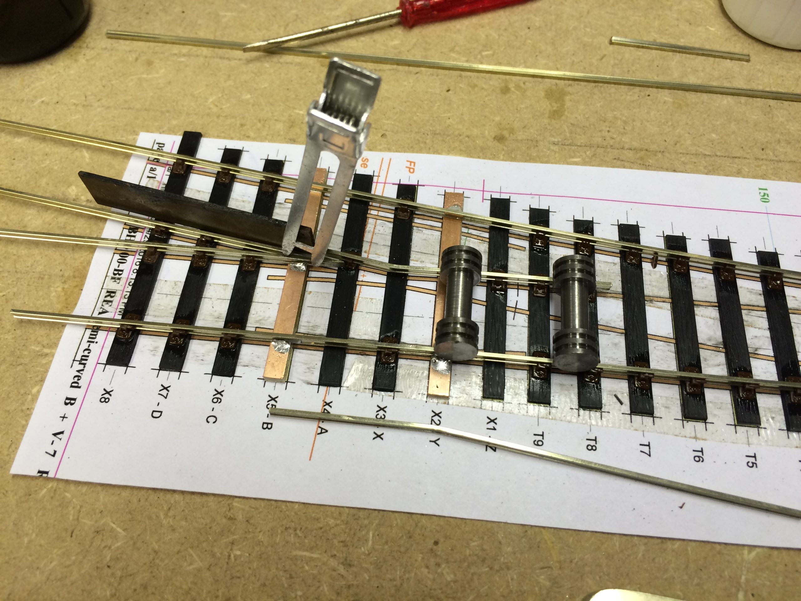
Although the key to building a reliable point is using track gauges to get the spacing right, I always start with a template. In this case it’s one printed from Templot, but you can but them. This shows roughly where everything should go.

Using a mix of plastic sleepers and copperclad – see this blog for why – these are held down with double sided tape.
I normally start with the V, shown here in the alignment jig being aligned, then freshly soldered with high temperature solder.


I generally start fixing the rails down with the straight rail, if there is one. The plastic full chairs are threaded onto the rail (the right way round, with the chocks sticking out in the direction of travel of the trains). Here you can see the chairs already on the two stock rails, and also on the V. Around the V, you need to trim the chairs so that they fit, as the C&L traditional chairs only come I two basic types – the normal chair as shown here and the slide chairs. Around where the check rails will go, I miss out a couple of chairs on each stock rail – to allow to chairs to go on the check rail. But you also need to trim off the inside of the other chairs where the check rail will go so it can align properly.

I then do use the plan to align the first rail to be fixed down, and get one chair at one end well stuck down with Butanone (make sure you have good ventilation).
When that rail is in place, the V goes down, using roller gauges to ensure its parallel with the stock rail. That is followed by the other stock rail, using the same principal as the first – fix the chair at the tie bar end using the gauge, then when the solvent is dry fix the chair at the other end. Then using the plan as a guide, curve the rail in at the middle to give a smooth curve, gluing the chair near the V first to make sure that’s to gauge, then work along. At this stage I soldered the V and stock rails to the copper clad sleeps to make sure it stayed square.
The next stage is to bend and fix the rest of the common crossing in place – the ‘wing’ rails. It’s obviously important to get a nice clean bend, and to line it up so that the wheel have a straight passage through in both directions. Here’s a flange gauge to check its straight and the right spacing, a hair clip to help it press up tight and roller gauges off the stock rail. The other rail is below.

Here’s the complete common crossing, together with check rails. Where there aren’t chairs on the rail itself (as you can see by the near check rail – there are chairs on the check rail there to hold it firm), I use half chairs cosmetically and glued them in.

Next come the switch rails. I cut the rails over length initially, then using a filing jig (you don’t have to, its quicker though), filed down the rail to the correct profile. Once filed down, I slid on the chairs and trimmed the rails to length.
As these are being controlled using the Exactoscale under-baseboard Tortoise motor mounts, they need dropped from each switch rail. I have normally used nickel silver, but had run out so have tried steel piano wire. It’s bent to shape and filed flat, then soldered to the rail with silver (221) solder.
Then I fixed the chairs in place one rail at a time using the gauges, and an Exactoscale insulating fishplate where it joins the common crossing. You can see the other blade with piano wire attached above.

Slide chairs are added (being carful not to push the rail in), the cosmetic stretched bar is soldered carefully to the inside of the swichbaldes, and the final bonds made between rails and copperclad sleepers.

How long did it take? Around 2 hours. And yes the first will probably take you a bit longer but they get quicker quite quickly, make much more realistic track and I find it’s very fulfilling.
You may also like...
Thursday Track Nights
We are open on Thursday evenings from 7pm to 9pm at our Keen House clubrooms. Visitors are welcome, please come along and introduce yourself.
Address:
Keen House, 4 Calshot Street, London, N1 9DA
Become a member