Track building – Part 1
Tom Cunnington
27th December 2015
6 minutes
One of the more frequent questions I get asked at exhibitions is how the track is built. Modelling in EM there isn’t much choice for anything other than plain track, but my track building goes back to my teenage OO days.
Despite living only a couple of miles away at the time, I originally stumbled across The Model Railway Club at a Model Engineering show at Wembley Conference Centre when I was probably around 11 or 12. A demonstrator (to this day I can’t recall who) was busy making track, and after a moment of asking myself why would anyone bother, I suddenly saw why, as it looked infinitely better than the Triang and Hornby track I had at home. The demonstrator explained what he was doing and why, and encouraged me to ‘have a go’, and in the process encouraged me to visit the next IMREX (also at Wembley at the time) and Keen House.
After visiting a few times when I was under membership age, I joined The MRC as soon as I could at 14, and by getting involved with the “New Annington” could see what the team had achieved – I think every piece of track on the layout was hand built, certainly the scenic sections.
My first track building experience was an SMP beginners kit, with the plastic track base to make things easier, then I progressed to a copper clad kit. At the time, the kits were cheaper than new RTR points, made much more prototypical looking tracks, and could be adapted to build the plan I wanted, rather than me designing a layout around the available geometry. Initially these were for my home layout, but in time I built much of the track for our rather more adventurous prototype based school layout, which worked surprisingly well. (There’s a pint at the Keen House bar for the first person to spot what the layout was based on…).
When I made the move to EM, once of the reasons was that I enjoyed making points, and the time taken for EM points is no different to OO, so I might as well get a better representation of the prototype for the effort by having a more accurate gauge. In OO I had only build copper clad points (soldering rail to copper clad PCB strips), but I took the opportunity to move to the C&L system of gluing plastic chairs that grip the rail to plastic sleepers. The plastic chairs and grain on the sleeper look more realistic than the PCB with a gap cut in the copper, and the solder. They are aslo slightly easier to adjust as you build and less likely to lead to burnt fingers.
In OO I had used SMP paper templates, cut up and put on a curve as necessary with V’s files and aligned by sight, but by the time I came to EM in around 2003, Templot was available enabling me to create templates to suit the location and to ensure the geometry worked. The EMGS supplied some jigs to help form the switch blades and the V-s and common crossing acurrately, which whilst pricey have been worth the investment for me. As an aside, if you are only making a couple of points, or want some confidence in making your first point, then buying the ready made common crossings and switch blades makes sense; in fact for Minories I bought the switch blades ready milled as the cost was relatively low, but the relative price seems to have gone up recently and once in a rhythm they are fairly quick to make.
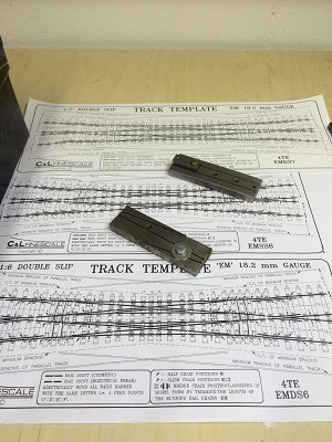
“Exchange Sidings” was built from Templot templates using C&L plastic components throughout, and initially worked well.  However exhibition layouts go through a range of temperatures, sometimes changing very quickly from a cold hall overnight to a very busy warm hall during the day; and in one case with the low winter sun blasting onto the layout through a large glass wall turning the venue into a sauna. With the C&L system, the rail is free to move in the chairs and I had a series of issues, including section gaps closing up causing short circuits and after one show the heat had actually altered the relationship of the common crossing leading to regular derailments. I ended up rebuilding the points on the layout, and whilst wanting to retain the cosmetic benefits of the C&L chairs, wanted to stop the rails from moving. So I put in a number of soldered copperclad sleepers at key places to create a “box” structure to hold everything true. The picture here
  shows a couple of entirely plastic component points, one of which has started to fall apart, and at the bottom a hybrid point with enough soldered construction to keep it together. The location of the soldered sleepers isn’t exact (and this is an early one I’ve kept for demonstrations), but I try to have one at each end, one through the common crossing, one at the last fixing point of the switch blades, and I now put another about half way along where the slide chairs are to hold the stock rails in a fixed position so that they don’t close against the switch rails in heat. By ‘gapping’ the copper clad just inside the rail on the rail nearest the viewer, most people see the majority plastic chairs, and don’t spot the soldered joints. The copper clad does provide extra benefits in providing electrical connections in the point that would otherwise need extra wires.
The old school layout above (hint – 1950s terminus) had a number of complex points, including a scissors on a curve, three way points and both single and double slips. That was getting on for 30 years ago, and since then I have had no need to do anything more complex than simple turnouts. But I have reached the point where I want to expand the fiddle yard on Minories.  It is currently a 6-road traverser, which still works well but has limitations. When it was built, having enough stock to fill it seemed extraordinarily ambitious. But not only have I gradually increased the amount and variety of stock, but the limitation of having the traverser so close to the scenic section hasn’t gone away. The current traverser is as big and heavy as I can easily carry (and the size of the car roof box), so the replacement needs to be a more traditional affair with points so I can make it wider, and with board joints make it longer too to increase the storage. I don’t want to waste too much space with long fan-outs, and as a terminus fiddle yard (at least initially) each road need to be able to access both the arrivals and departures line. So I think the answer is a scissors crossing with double slips to start the fan out. I have worked out how to do the scissors in Templot, but was struggling to get a full Slip template so since these will be simple straight geometry have gone “retro” and bought the C&L paper plans. As there are in the fiddle yard, I think copper clad will be the most robust method of construction
My original switch blade filing jig wasn’t returned by a member when he left the Club a couple of years ago, and after waiting in vain for the EMGS to restock them (the cost was irritating, the lack of availability much worse) I found the Scalefour Society stocks them.
And so Christmas has delivered me a new filing jig, and my 2016 modelling will start with filing about 10 pairs of switch blades, and making 10 common crossings and then see what I’ve forgotten about making slips over the last 30 years. I’ll let you know…..when my fingers have recovered enough to type.
You may also like...
Thursday Track Nights
We are open on Thursday evenings from 7pm to 9pm at our Keen House clubrooms. Visitors are welcome, please come along and introduce yourself.
Address:
Keen House, 4 Calshot Street, London, N1 9DA
Become a member