Making Use of a Garden
John Jesson
18th May 2021
13 minutes
Introduction
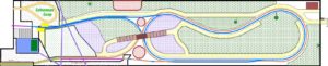
For a number of years, I have contemplated building a railway in my back garden so that I could run by small collection of Gauge 1 and G scale models. I undertook a lot of planning work on the CAD programme on my computer. Some of the ideas were unnecessarily complicated, but I eventually ended up with a plan that seemed to fulfil all requirements. As well as the aforementioned large gauge (45mm), there would also be a 16.5mm circuit so that I could run my HO European-outline stock. I had even devised a means of connecting this circuit to the main railway indoors. The final plan is shown below and, towards the end of 2020, I finally took the plunge. The other person seen in a few of the pictures is Phil, my builder and friend, who did all the hard work!
Throughout I have taken a lot of photographs, not all of which are included in this article. This accounts for the gaps in the numbering of the illustrations.
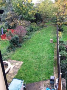
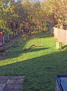
As it was at the end of October 2020. The useable size of the garden is roughly 40m x 8m with a further area at the rear that is fenced off and used as a combination dumping area, wildlife reserve and burglar deterrent. It’s pretty much a jungle, especially along the left side, where the bushes have grown unrestrained for many years. While the grass looks nice and green, it’s very uneven and with a lot of weeds.
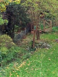
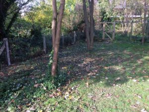
Towards the back of the garden in October 2020, showing the gate into the rear area. The jungle on the left is obvious, as is the condition of the garden next door.
A week into November, an awful lot of the untamed jungle along the left side had been cleared. Sitting on the grass is one of the larger tree branches that had been removed.
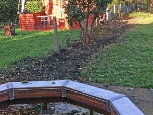
While digging up the bushes, a couple of items were unearthed. One was a dinosaur – a very small rubbery plastic one that is seen here guarding the all-weather loop that connects the two levels of my indoor railway.
Compare with picture 2.
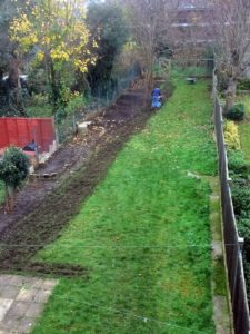
A few weeks later at the end of November 2020. The jungle has been cleared and a start made on rotavating the entire garden area.
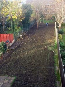
All rotavating done, leaving a very muddy mess. This was in the first week of December 2020. All the loose surface material then had to be cleared – a dirty and back-breaking task.
During the next four months the top layer of mud and weeds was removed and dumped in the rear (fenced off) part of the garden. Work was delayed by the moving of the old (plastic) garden shed to the rear of the garden to make space for a new shed.
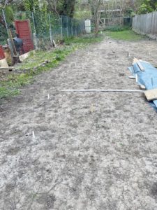
It’s now the end of April 2021. The waste material has been removed and the dry late winter/early spring has dried the mud out. Of course, nothing stops the grass and weeds from sprouting anew in the spring, so parts of the bare earth are turning green again.
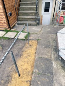
The locations of the supports for the railway have been marked – that’s what the short white posts are.
It’s easy enough to determine the co-ordinates for these supports on a computer. It’s not so easy to transfer them to the ground. After a couple of false starts, a line was laid the length of the garden at 4m from the RH fence at the house end. Its distance from the RH fence varies over the length of the garden because the fence does not run in a straight line. At 10m, 20m and 30m from the house, cross lines were laid, forming a grid. The post markers were then positioned by measuring the distance from the grid lines. Visible at the back of the garden is the plastic garden shed, now in its new location.
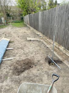
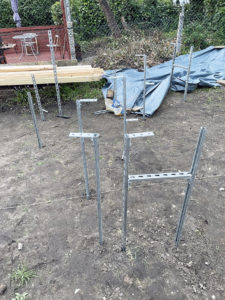
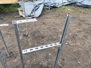
The railway supports are Unistruct, which can be hammered into the ground. This works fine in most cases, but some have to be cemented in place, either because of an obstruction or, as here, because of what will be hung on the top of the post. The obstructions are usually very large stones, tree roots or, in a couple of places, an old air raid shelter foundation.
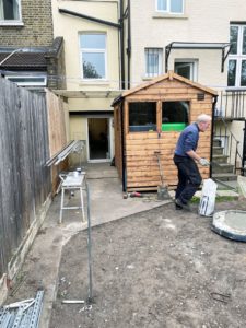
A general view of the back of the house with the new shed and, to its left, the back door of the workshop.
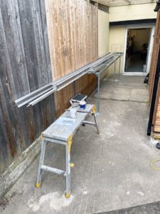
A closer view of the rear of the workshop, showing where the railway will emerge into the garden, and the structure that supports it alongside the shed. On this structure are several aluminium constructs – more on these later.
Connecting the garden section with my indoor HO layout required a lot of thought. Initially, I had intended to connect using the protected outside loop (which I call the Laburnum Loop, as it runs around a laburnum tree), but found another way. It’s intended to only use the outside garden tracks in fine weather, so I’ve made the connection through the opening window in the back door of my railway room. The inside and outside parts are connected by a 5m long aluminium ‘T’ section. The garden end is supported by the wooden post seen here (in line with the white door hinges).
Aluminium sections to engineer a solution
I’ve mentioned that the plan included both 16.5mm and 45mm gauge tracks. In an aberrant moment, I wondered if I could combine both gauges in one (only running trains on one of them at the same time, of course). The answer is yes – 16.5mm track sits very nicely inside 45mm track. This wouldn’t be feasible for most of the circuit, as the smaller gauge is at a much lower height above ground level than the larger (by nearly half a metre).
Then I started to think about how the two gauges could “combine”. The very different standards (in particular, flangeways) precluded a flat solution. However, European HO models are less than 40mm wide (generally 35mm) so would fit between the 45mm gauge track. After some thought and internet searching I came up with a rather fantastic construction of aluminium sections bolted together to allow a 16.5mm track to rise gradually within a 45mm track, from clearance height at one end to the same height at the other.
The whole thing is 7.5m long and the main girders are of 4in x 1in aluminium ‘U’ section on edge. Between these girders, the trackbed for the 16.5mm track is 40mm x 20mm aluminium ‘U’ section with the flat section on top (i.e. inverted). At the end of the greatest height separation (the garden end), additional 1in x 1in ‘U’ sections are added to the bottom of the main side girders to accommodate the fixings for the 16.5mm trackbed. The side girders and the additional girders are all bolted together with 1/4in bolts, using spare sections of the 1″ x 1″ ‘U’ to strengthen the joints between the main girders (there are three girders each side, 2.5m long). As aluminium is a poor conductor, brass strip is bolted to the top of the main girders as the running rails for the 45mm gauge track. As with the brass strip track construction on Copenhagen Fields, Minories and Orchard Wharf, the bolts used are countersunk.
The 40mm wide section along the middle needed to be spaced away from each of the side girders by 2.5mm each side. It will not have escaped your notice that the use of normal bolts to fix the two side girders and the central girder together means that both side girders are connected electrically. This is not a good idea for 2-rail electric systems. The solution has been to use 5mm nylon bolts/nuts/washers. The nylon washers come in two sizes, of two thicknesses. The larger is 1.5mm thick, the smaller is 1mm thick, so one of each on each side gives the necessary 2.5mm separation. To give more rigidity, the two side girders are strengthened by 5mm acrylic sheets connecting them at intervals along the bottom edge. It remains to be seen how well the whole structure retains its 45mm gauge along the top edges. I think it should be OK but I have also worked out how to further stabilise it should it become necessary.
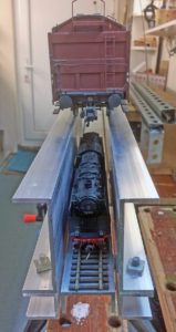
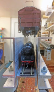
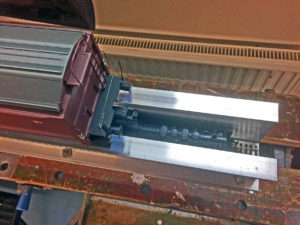
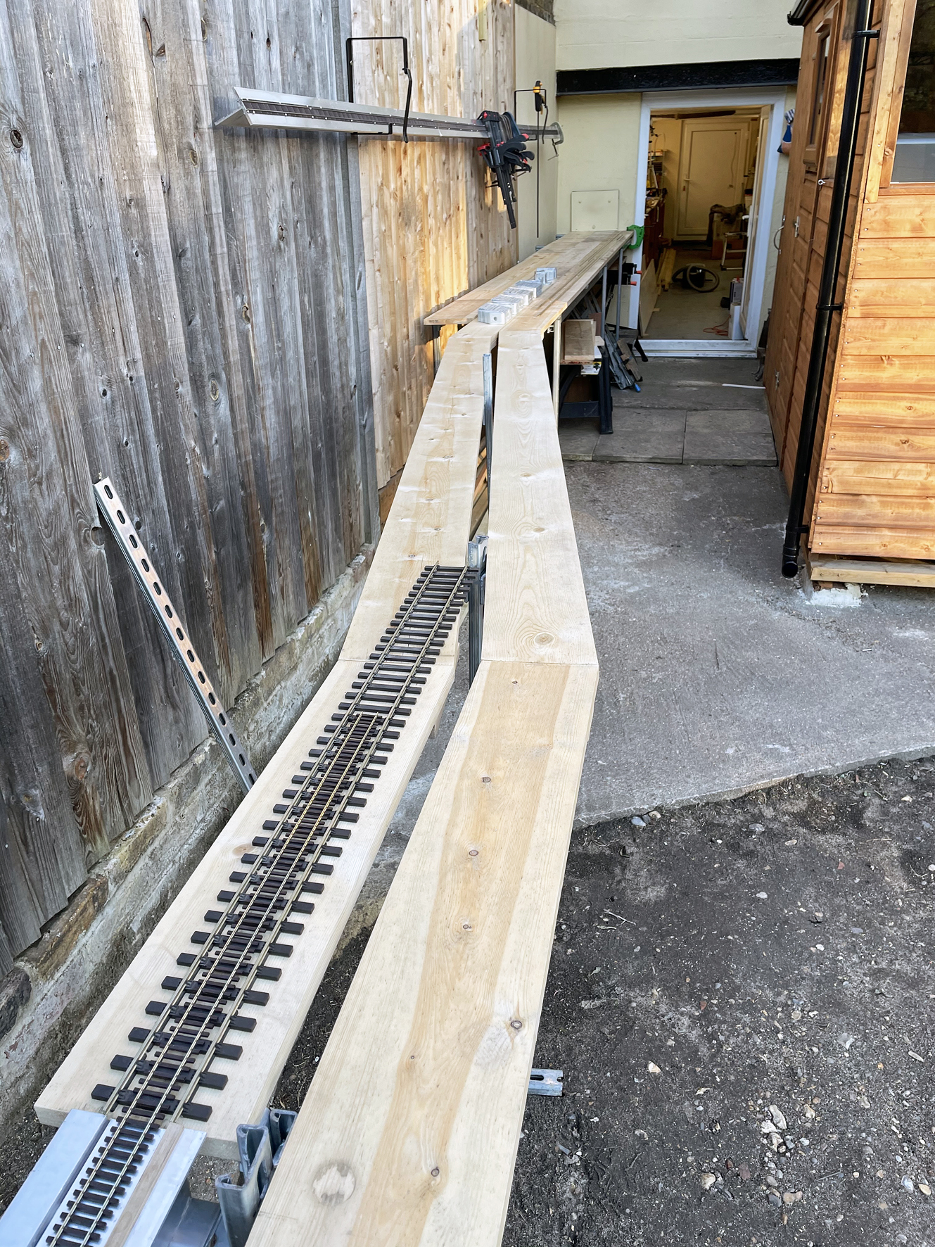
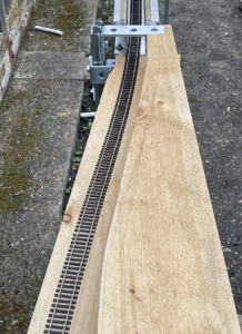
The main side girders came in 2.5m lengths; the illustrations show 2/3 of the length (5m). At this stage, the main side girders, lower extension girders and the 16.5mm trackbed girders have all been bolted together. There is a further 2.5m section to be added. Yet to be added are the acrylic sheets and the brass “rails” for the 45mm gauge. As can be seen, there is adequate clearance for the HO rolling stock between the side walls. The end shown is the garden end, where the 16.5mm track can curve away from the 45mm track above it. At the other end, the 16.5mm trackbed is almost at the same level as the 45mm, the “almost” being because the 16.5mm track will run on the sleepers of the 45mm track.
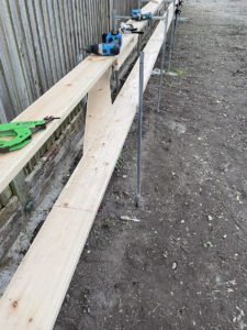
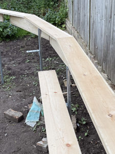
The plan called for the 45mm tracks to be at the same height all the way round the garden, so the first of the timber track bases were installed outside the workshop, where a 4m long bench was constructed. The 7.5m aluminium construction was positioned first, but not fixed (except by a couple of clamps). Boards (150mm x 22mm, treated with wood preservative) were then continued from the decking outside the workshop, cutting as necessary.
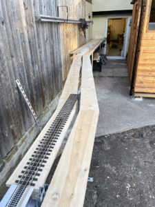
This first stage is illustrated here. The bench outside the workshop with the angled boards heading off towards the garden. At the bottom left corner is the end of the aluminium construction with tracks of both gauges in position for height adjustment.
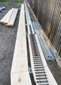
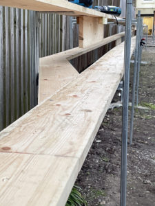
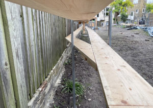
The view the other way showing the length of the aluminium section. The board alongside will carry the return loop.
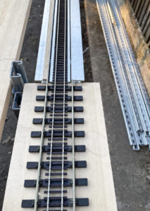
A closer view of the transition between the aluminium section and the timber-based track. At this stage, the brass running “rails” are not fitted, but one has been placed in position to get heights right.
Best laid plans!!! Somehow, when calculating the clearances at the garden end, I mucked it up. There was not enough clearance for the HO trains! Fortunately, there was a way round the problem. This shows the start of the solution. There is enough clearance for the trains to run below the steel bracket, so this has been secured at the right height to support the 45mm track directly. The top surface of the wood is flush with the top surface of the bracket and has been cut to allow the HO track a clear run. Still to be done is to instal a support above the HO track to support the 45mm track.
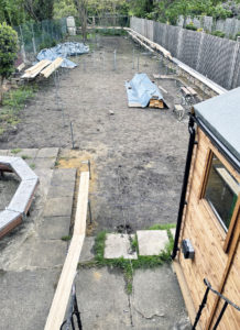
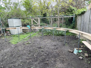
This is a general view of the state of play at the end of 14th May. Most of the supports have been installed and trackbeds have been installed the length of the garden down one side. The pile of timber covered up partway down the garden is newly-delivered timber waiting to be treated. On the left side is the remaining treated timber from the first batch with, behind it, a large area of ground covered up to discourage the growth of what was there before. In the foreground, the start of the connection out of the house to the rest of the HO garden tracks.
A forest of steel supports where the triangular junctions meet the main circuit. It looks confusing, but all will become clear in time.
Trackbed construction
Support structure
Unistrut, as I’ve already said, is used for the main support members. This is a heavy steel flat ‘U’ section that is tough enough to be hammered into the ground. There different sizes – I used P3300T, which is 41mm x 21mm and comes in 3m lengths. Along the length on the flat side are slots 25mm x 11mm, spaced at 50mm centres. A confusing variety of fittings is available but my needs called for only a few of them; brackets, bolts, washers and nuts. The brackets used are all 90° (other angles are available) and have fixing holes on both legs – those I have used have 1 hole on one leg and either 1, 2 or 3 on the other, according to use. the leg with 1 hole is approximately 2″ long, 2-hole 3¼”, 3-hole 5″. Bolts, nuts and washers are all 10mm but, as well as standard hex-head, there are channel nuts, which locate inside the Unistrut section. Included are a couple of photos showing the components and how they fit together. [Garden 45] [Garden 46]
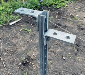
The pair of “2×1″ brackets on the same post will eventually end up at the same height supporting an 8” wide surface for an area that contains three HO tracks side-by-side. The post will be cut (with an angle grinder) once the exact height has been determined. One of the brackets has only limited vertical adjustment (that bolted through the “base” of the “U”) so, as long as the post is not concreted in position, it can be hammered a little further in, should this be required. Alternatively, the angle grinder can cut away the web between two adjacent slots to allow more movement. This does not compromise strength, which is ample for the needs of its usage. In some locations, a pair of posts has been used, with the open faces of the “U” facing each other, and a crosspiece installed. This arrangement has been used in several locations for when two tracks are merging and two boards have to be supported at the same level. It has also been used along the long straight section, where there are two HO tracks each side of the (higher) 45mm track. In this usage, the crosspiece is at the higher level, as seen here. [Garden 50]
The trackbeds
The trackbeds for both large and small scales are made the same way; a flat surface of 6in x 1in planed timber (which comes out at 150mm x 22mm) with a vertical section of the same material at the joins between flat boards. One fairly short length has an 8in x 1in surface. As flat boards are prone to warping, additional pieces of timber are screwed under the joints to get a flush surface. All joints are screwed (not nailed).
While the HO track is almost entirely on an incline so that it can get from the lower level connection to the inside layout, to the higher level into the workshop, the larger scale (45mm track) is level all the way round the garden. So the natural starting point was to begin with the larger scale trackbed. Once this was installed and levelled up, it was easier to check that the planned height difference between the two gauges was being achieved. The planned gradient for the HO tracks was 1:100.
Getting the boards at the right height is fairly straightforward, but can be fiddly. The first section to be done was (of course) the long straight part alongside the RH fence. This was quite easy, as Phil had done all the hard work of getting the crosspieces at the right height.
The HO boards started at the end of the aluminium section, falling at 1:100 more-or-less parallel to the 45mm gauge boards. The “more-or-less” is because the planned alignment is slightly different owing to a late amendment to the plan.
The 1:100 gradient is fairly easy to achieve. One of my spirit levels is 600mm long. If a 6mm spacer is put under the “downhill” end, it’s only necessary to adjust the support brackets until the spirit level registers level. This can never be 100% accurate, but as the large gauge is at the same level all the way round, the separation of the two levels gives a good cross-check.
This area, where the line climbing towards the workshop diverges from the continuous circuit, was critical and a little awkward to get right. The reason was changes of gradient – from the junction, the continuous circuit falls in both directions. Changing gradient when the baseboard is an inch thick is a little more difficult than for most indoor systems. I found the best way of building this part was to make everything level, then introduce the gradients once everything was joined together.
The far end of the garden. The trackbed for the 45mm track starting its curve at the higher level. At the lower level, the HO trackbed has not yet been extended beyond the straight boarding. Getting the curve (about 220° of it) right isn’t as easy as you might think. The angle between boards at their joints needs to be as equal as possible, and the boards need to be as near the same length as possible. This is to try to maintain a smooth curve without the track running out of support on either inside or outside. This is especially important where the 45mm track is concerned – being wider, there is less room for error.
The distance between supports is between 1100mm and 1300mm, so I cut enough 1300mm long boards to go all the way round. I then spent a long time balancing them on the support brackets and clamping them in place, then going round the curve adjusting their positions until I had both board lengths and angles as equal as I could get them. All the boards were then carefully marked and, starting at the end of the long straight section, cut and fixed in position. The fixing in position was by means of the vertical boards initially. Later, once the whole circuit was in place and checked, all of the horizontal boards were secured to the support brackets by a single screw/washer up through the bracket into the wood. This is done at all support brackets around the garden.
To be continued…..
One thought on this post
Leave a Reply
You must be logged in to post a comment.
You may also like...

Thursday Track Nights
We are open on Thursday evenings from 7pm to 9pm at our Keen House clubrooms. Visitors are welcome, please come along and introduce yourself.
Address:
Keen House, 4 Calshot Street, London, N1 9DA
Become a member
Isn’t that fantastic? Very English Eccentric – and excellently so. Nothing wrong with that.
Due to the fact that global warming has not yet hit the UK, it would probably help to have some sort of removal cover to save your work from the rain and frost. Your building method also looks like you could modify and extend it fairly easily. It would be interesting to know whether you are planning powered rails, or batteries – and whether you might use wireless controls?
Brilliant: good luck with it all.
DL