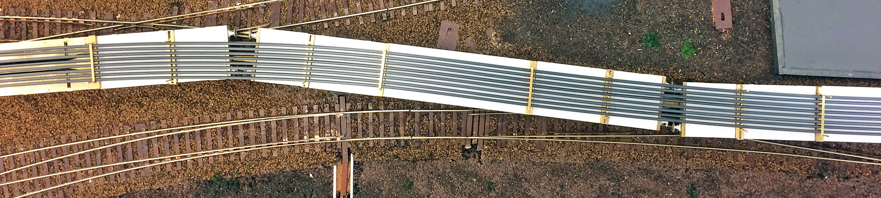
A Long Welded Rail Train
John Jesson
29th August 2020
14 minutes
Several years ago, a French firm that makes plastic sections (something like Evergreen) introduced plastic rail section in different sizes. The smallest is equivalent to code 80 and I bought some at one of the exhibitions in Germany. Moulded in dark grey plastic, it is flexible enough to be easily curved. So was born the idea of a loaded LWR train.
My first thought was to build one of the trains built by Cowans Sheldon in the 1980’s. I even went as far as obtaining drawings from CS. However, I felt the challenges would exceed my abilities. The whole project was put on the back burner for a while, but then I got involved in Tom Cunnington’s proposed “Canonbury” layout. The idea of a LWR train was re-born, but as one of the 1970’s trains with a single ‘layer’ of rails conveyed on converted SR EMU coach chassis’.
First task was finding a suitable chassis. There are no suitable SR EMUs on the market (the prototype vehicles came from 4-COR and 6-PAN units) and, in any event, the chassis would need to be flat on its top surface and be heavy. Compromise number 1 – I decided to use Comet Models Bulleid coach chassis’, which are quite a close match. Next problem was the bogies. The original EMU bogies were retained on the converted wagons (‘Manta’ & ‘Marlin’ were the code names) but, again, nothing available on the market. Compromise number 2 – I’ve used Comet Models SR 8ft steam stock bogies. Again, these are fairly close to the EMU bogies in appearance. The EMUs were fitted with rather distinctive buffers. These are available in 7mm scale, but not in 4mm scale. Compromise number 3 – the closest I’ve found are SR/Pullman buffers from 51L. There are definitely differences, but I am hoping that viewers at an exhibition will be more interested in watching the train, rather than counting the rivets.
The big question, of course, is whether 8 rails can be laid on the wagons and be flexible enough to go round model corners. The only way to find out is to make the train. If the project falls flat on its face, at least the train can run empty.
If I remember correctly, the rails were in either 300ft or 600ft lengths. This equates to either 5 or 10 vehicles. Having obtained enough chassis and bogie kits for 5 wagons, the first job was to assemble the chassis kits. Comet rely a lot on a fold-up bodyside to maintain rigidity, but this has to be cut off, as the floor needs to be completely flat for mounting the bolsters. The completed wagons will also need to be heavy, in order to resist the sideways forces from the rails. As the wagons are not seen from the underneath, rigidity is provided by two 4mm x 4mm strips of brass, 125mm long, soldered to the underside, spaced 5mm from the inside of the solebars and central between the bogies. This gives some additional weight, rigidity and allows unrestricted movement for the bogies.
One of the more complex problems has been to devise a coupling between the wagons. It has to be rigid, as any sloppiness could lead to running difficulties. It also must increase its length on curves. This is for two reasons; first is visual (I don’t like big gaps between vehicles), second is to prevent buffer-locking on curves (the rigid coupling should allow the train to be propelled without buffer-locking). The design of the coupling was done on my CAD software and, as the design progressed, more and more details were needed on the drawing.
The wagon needed to be a complete underside plan view showing the overall size (255mm x 33mm), inside dimensions (251mm x 29mm), buffers (drawn as blocks 6mm wide x 5mm long), bogie pivot points, wheel size & position and bogie fixing brackets.
Once the wagons had been drawn, a straight track was drawn (18.2mm gauge with a centre line) and two wagon drawings “placed” on it with the buffers touching. This was the start position. Next stage was to draw a 1m radius curve and position the two wagons on it. Then each wagon was rotated so that the bogie pivot points were aligned with the track centre line. This involved shifting the wagon on its ‘Y’ axis slightly to allow for the track curvature. Once one wagon was done, the other was done, using the same displacement and rotation figures (except the rotation was in the other direction). Then both the wagons were moved apart so that the buffers just touched, necessitating another slight alteration to the rotation and alignment of both wagons. Tom then pointed out that the biggest problems he had on “Minories” occurred on the reverse curves at the station throat, so I then drew a 1m radius reverse curve without any transition or straight section between. Entirely unprototypical, but if the coupling allowed such a brutal change it should be OK on anything Tom could dream up on “Canonbury”.
The principle behind a coupling that can change its length is to make it in the form of a letter ‘T’, with the vertical arm in line with the length of the vehicle and the top of the letter across the vehicle with a ‘stop’ that prevents the coupling from moving backwards. The coupling needs to remain centred at its theoretical pivot point. When the coupling is displaced, as on a curve, it pivots around its nominal centre point. As it cannot go ‘backwards’ because of the ‘stop’, it is pushed forward (that is, towards the buffer beam), thus extending the length of the coupling.
The vertical arm of the ‘T’ needs to have a slot in it, although it is easier to make it from two sections.
There was a lot of trial and error involved in the design work. Initially, I tried a short coupling, just behind the buffer beam. This did not work as the sideways displacement was too much, especially on the reverse curve. Without going into all the variations, the end result uses the bogie pivot as the nominal pivot point for the coupling, with the ‘stops’ each side of the bogie support bracket. These ‘stops’ are positioned slightly away from the bracket, as the bracket is fixed to the bogie, not the underframe, so has to move. The space does not need to be more than 0.5mm. Once the basic design was settled, I looked at the separation between wagons. The ideal would be for the buffers to touch on straight track, but this is not really practical on most layouts. I settled on a separation between buffers of 2mm. Later, it would be possible to reduce this, if a smaller gap proved to be practical.
The main arm of the coupling (the drop-down bit of the ‘T’) is more complex than might be thought. At the pivot end, there is a pair of strips running each side of the bogie pivot screw. The pivot screw acts as the nominal pivot for the coupling, and the two strips allows movement on the wagons longitudinal axis. The cross piece of the ‘T’ is almost the full width of the chassis underside and is as close to the bogie centre as is possible. Its rearward movement is restricted by two blocks fixed to the underside of the chassis, each side of the wagon. As these blocks are between the bogie wheelsets, they do not restrict bogie movement. The section between the wagons also has to be lower to clear the bottom of the buffer beam. Finally, there has to be a crosspiece to prevent the coupling from being pulled too far. There are 11 pieces in each coupling, not counting arrangements for springing and retaining.
Yes, springing. The coupling has to be held back against the stops, so some sort of spring is necessary, in order to accomplish this, but also allow the coupling its movement on curves. Commercial manufacturers use various means to do this, often combining in the design a spring and a means of preventing the coupling from being pulled towards the end of the vehicle until it has displaced from the centreline slightly, then guided by a curved slot. This latter feature means that only a light spring is required, but is a little too sophisticated for me to reproduce. I’ve used a tension spring, guessing at how much tension was required. It needs to be strong enough to keep the wagons together when starting and on a gradient, but not so strong as to cause difficulties when entering a curve. I’ve made the attachment points adjustable but my guess seems to be on the money during the initial tests.
For the end couplings, a similar arrangement was used, but with differences. Tom uses Kadee couplings, so the height of the longitudinal bar (the vertical bit of the ‘T’) was adjusted. Additionally, of course, the Kadee end of the coupling needs to be supported.
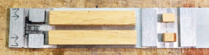
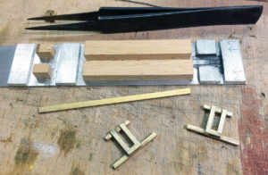
The jig for assembling the coupling bars, made mainly from aluminium strip. All the soldering is done at the left end – all the rest of the jig is to hold everything in the right place
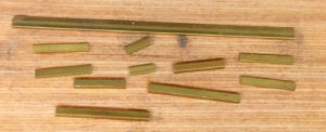
The bits that make up a coupling
First step in assembling the coupling. Two 2mm x 1mm strips in place, separated by the 3mm x 1mm strip (placed so as to hold the strips apart but not be accidentally soldered). Long 2mm x 2mm strip placed on the end of the longitudinal strips
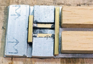
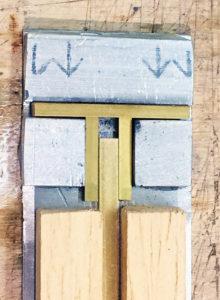
3mm strip removed and assembly turned round. Shorter piece of 2mm x 2mm placed and soldered. Note the pencilled arrows that mark the extremities of the 2mm square pieces so that they are centrally positioned
Two end pieces assembled and cleaned up. Short 2mm x 1mm pieces added across the ends of the longitudinal members. The tweezers behind the jig are a very old pair that have seen better days, and are now used for building things that need to be soldered
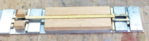
This shows how the other end of the jig comes into play. Both end assemblies are put into place and the 3mm x 1mm strip placed on top. Here, one end has been soldered, then everything will be turned round and the other end soldered. Doing it this way ensures that the long strip is supported level
Trial and Error
I’ve mentioned trial & error when designing the coupling bar. No matter how much thought is put in, there will almost always be things not thought of. So it proved here! I have had to alter the bogies to clear part of the coupling bar – in two places. Part of the bogie centre plate has had to be removed, and the cross-member that joins the two sideframe parts rebuilt. Neither job is particularly difficult, but I’m annoyed with myself for failing to anticipate the problems.
Having tried the set of wagons (they will end up with EM gauge wheelsets, but were temporarily fitted with OO wheelsets so that I could test through pointwork on my HO layout) the next task was to try to make the load. As stated at the beginning, plastic rail section is now available, which allows the necessary flexibility. But, and it is a big “but”, a line of rails (a full load is 8) changes length as it negotiates curves; the inner rail gets “longer” and the outer rail “shorter”. Therefore, all the rails need to be able to slide in relation to each other. At the same time, all the rails need to maintain separation from each other, and they must be fixed at some point.
When I was first thinking about the possibilities, my idea was to fix the rails in the middle of the train. This has been changed to fixing them at one end. The rails have to be fixed somewhere to prevent them, eventually, wandering off the wagons. One of the end wagons has an offloading chute, so the ends of the rails stop short of the end of the wagon, allowing movement. The logical place to fix the rails, then, is at the other end of the 5-wagon set. Additionally, although a 5-wagon set is being built initially, it is intended for an additional 5-set to be added. The rails on this set would have to be unfixed, attaching to the rails on the first set. so there will be a central fixed point.
Not forgotten is the fact that this train is intended for use on a portable layout, so needs to be easily assembled and disassembled for transport. A friend had a similar situation with his N gauge layout and full-length German ICE trainsets. Even in N gauge, these are 5 – 6ft long and are a pain to put together. He has built long, thin storage/transport boxes with rails, with a small ramp that can be attached so that a complete train can be driven under power in & out of its storage box. I’m planning a similar arrangement for the LWR train, with the two parts stored/transported side-by-side, suitably protected. No doubt, having built one box, I’ll have to build a second for Tom’s Freightliner train!
Bolsters
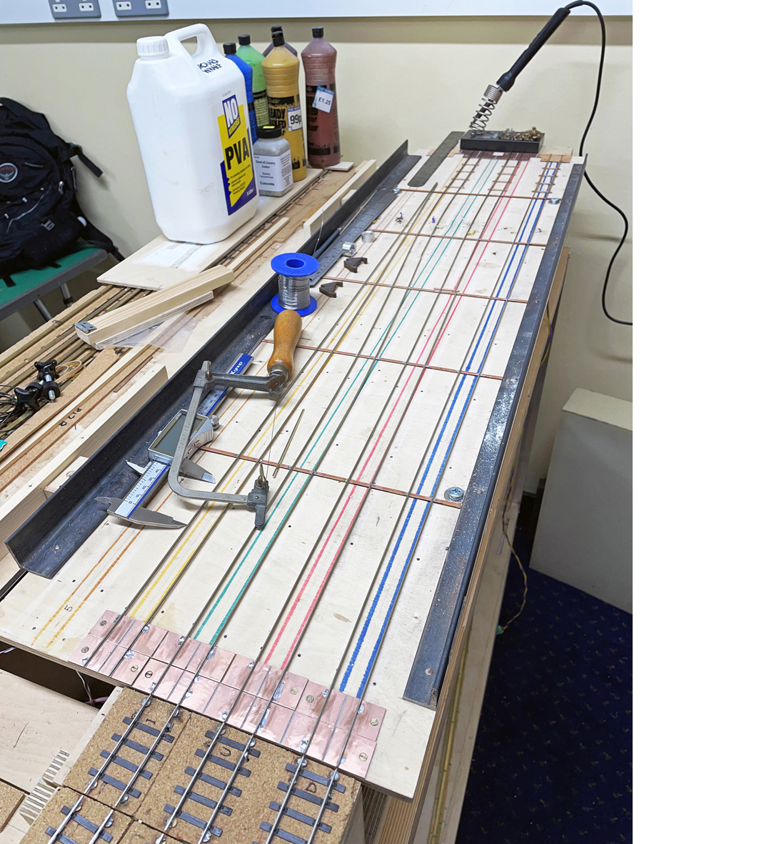
Back to the rails. I made up a number of plastic bolsters with plastic dividers. One of them had 8 rails glued in, then the rest were threaded on. At this stage, the chassis’ were still bare brass and the bolsters were temporarily fixed to the chassis with double-sided tape. Then, very tentatively, the set was pushed through pointwork on my layout. Not entirely successful. Each wagon has 4 bolsters – 2 more-or-less over each bogie pivot, the other two roughly 1/4 and 3/4 between the outer two (there is a fifth bolster, but without guides, in the centre). If all four bolsters are fixed, all the bending has to take place between the last bolster on one wagon and the first on the next wagon. This is quite a lot of stress. It worked in most situations, but my minimum radius of 1m was a little too much.
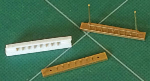
The standard fixed bolster. Left is one of the plastic card temporary bolsters I knocked up to initially test the concept. Bottom is a half-built block (intermediate spacers fitted but no long uprights). Top right is a finished example with the rail “retainer”.
The drawing board, as usual, was readily available to come back to. First thing was to throw the plastic bolsters out of the window; there is too much friction between the plastic surfaces. There is no changing the rails (they have to be plastic), so the bolsters would have to be made of brass. Second, I had used 1mm square section plastic as dividers. Round section mounted vertically would cause less friction and would also be easier to make. A series of 0.9mm holes drilled in 4mm x 2mm brass bar at 3mm intervals would allow 0.9mm brass wire to act as both dividers and the two extended uprights. Incidentally, the dividers are not prototypical – the prototype rails being heavy enough to not need them (in theory, that is; there is photographic evidence that the rails did sometimes start to ride over each other). Also unprototypical are the retaining bars I have used to hold the rails down. This is 1.5mm x 0.5mm brass with a hole each end to drop over the two bolster long uprights.
Each wagon has five bolsters, although the centre bolster is merely a support. The outer bolsters very roughly coincide with the bogie pivots, with the others more-or-less equally spaced. The placing seems to be standard, although the separation is not. Now consider; you have four bolsters on a wagon holding a load in a straight line, but that load extends onto the next wagon, where another four bolsters are holding the load in a straight line. When those wagons enter a curve, all the curvature of the load has to be on the short section between the end bolsters of the two adjacent wagons. That’s a wee bit too much to ask of a row of rails, even plastic rails. It also looks rather odd.
The answer was to make only the centre three bolsters fixed (two with guides, one without) and make the end pair of bolsters so that they have a degree of sideways movement on the wagon. The fixed bolsters are 4mm wide x 3mm deep. The sliding bolsters are the same outer dimensions, but are constructed of 3mm x 1.5mm ‘U’ section on its side, with a 3mm x 2mm central section with the 0.9mm uprights. This central section is free to slide from one side of the wagon to the other by about 5mm. At each end, a 4mm x 3mm brass plate is soldered to the ‘U’ sections to hold everything together. An initial test showed that the concept worked and looked likely to allow what was intended.
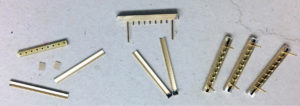
The sliding bolster. Left are the parts that make it – a central block, two channels and two end pieces. Centre, the block now has the 0.9mm rods fitted and each of the channels has one of the end pieces soldered in place. Right is a trio of assembled bolsters
The bolsters were all made (except for the centre ones, which will be added later). The sliding bolsters are fiddly to assemble, but work well. They allow a sideways movement of roughly 5mm (2.5mm each side of centre). I’ve fitted 8 bogies with ‘OO’ wheelsets (all I have) to allow testing on my HO layout. This is enough to test a train with 4 wagons and a full load of 1m lengths of the rail. The results were very satisfying; the train coped with a 1m radius continuous curve and a variety of reverse curves, both being hauled and propelled.
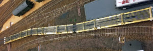
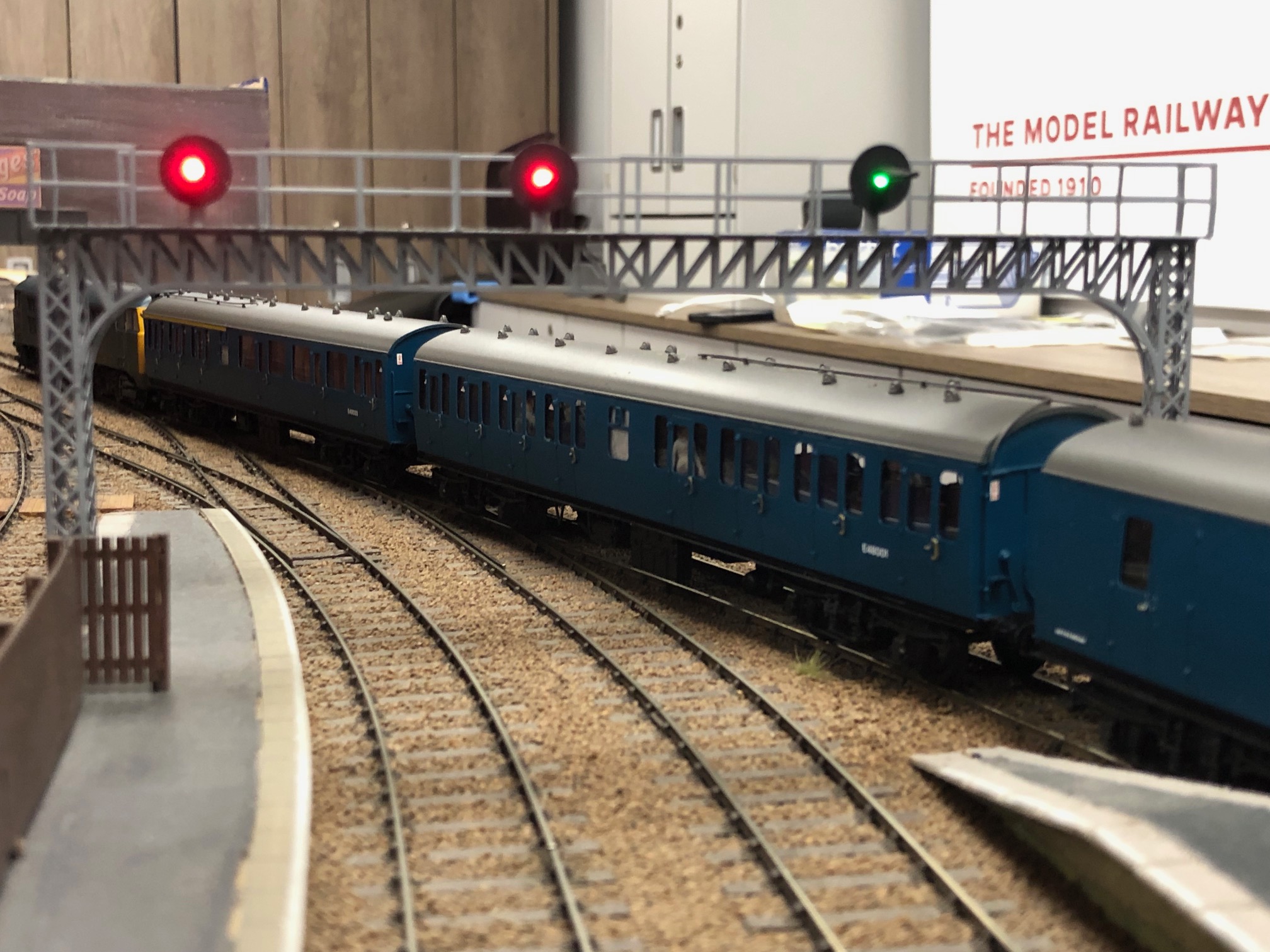
This was the first test with the brass bolsters. Only the two central bolsters were “fixed” in place (with rubber bands), the end bolsters being slid onto the rails but not secured to the wagons. It can be readily seen that, as the rails take up the curve, the end bolsters on the wagons are forced well out of place. It was after this test that I came up with the idea of sliding bolsters
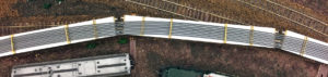
The same initial test, but on a rather less sharp reverse curve. After this test, I didn’t doubt that the train would run over the visible part of Tom’s new layout, but it will also have to run over the end curves and negotiate the storage yard pointwork
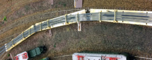
The central bolsters have now been fixed to the chassis, and the sliding bolsters manufactured and similarly fixed in their end positions. This was the crunch test, and it was a success. This is the same 1m radius curve as before; it can be seen that the sliding end bolsters allow some sideways movement of the rails. Instead of forming an almost perfect arc, the rails are now slightly straighter at the centre of the wagon and more curved between the wagons. However, the train could be both pulled and propelled without any problems making themselves apparent. Those problems, of course, will only make themselves known at the very last stage. This is, I believe, a manifestation of Murphy’s Law.
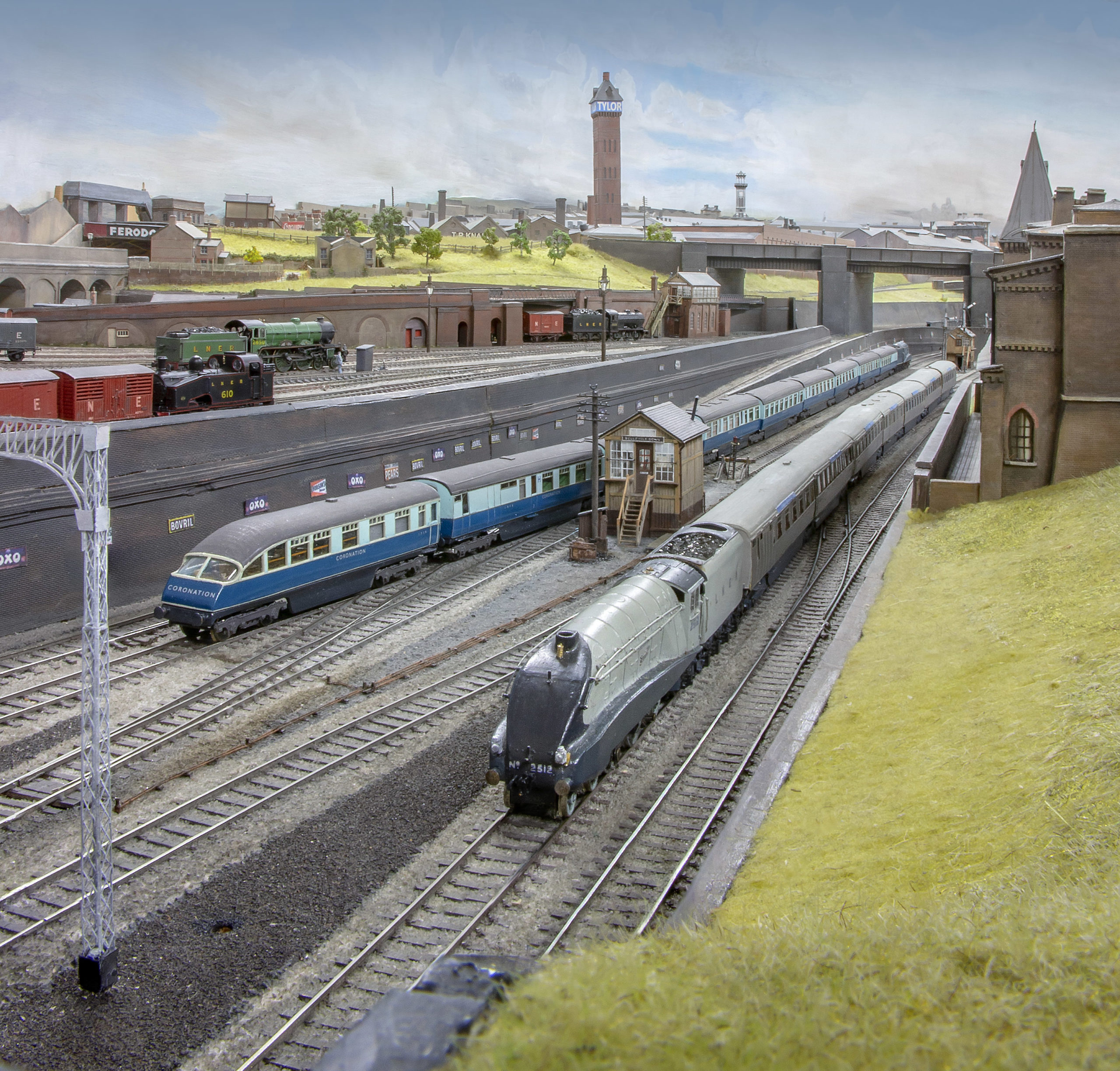
The header picture is of this test train on a reverse curve
Glue vs Solder?
It’s probably worth mentioning here about my various methods of joining things together. The chassis is brass, as are all the components to turn it into a wagon (buffer beams, strengthening beams, bogie pivots, coupling stops, etc.), but apart from the buffer beams, very little is soldered. Part of the reason is my lack of soldering skill, part that my large 90W iron is too large to get into confined spaces, and part the difficulty of accurately locating small pieces. The most reliable means I’ve found is epoxy resin, that gives time for fine adjustments and is stronger than cyano. The top surface of the wagon is 0.5mm plastic sheet. It is fitted between the bolsters and secured to the brass chassis with aliphatic glue.
That’s as far as the project has got at the moment. What I now need to do is finish the wagons and fit the outer ends with suitable couplings (these will be NEM boxes so that Kadees can be fitted, but also so that a plug-in rigid coupling can be used when I build a second 5-wagon set). Then comes painting and the inscriptions. I’ve already asked Ben Weiner if he will produce the necessary transfers, where none are otherwise available.
I still have to increase the length of the rails to 1200mm (scale 300ft). The plastic used seems to be ABS, so needs Butanone to have any effect on it. A butt joint is not feasible, so I’ll try to use some sort of rail joiner (each rail has to slide independent of the others). When doing this, I’ll have to make sure that the joints are well clear of any of the bolsters. Joining two sets of 1200mm rails together will be interesting, to say the least, but it won’t be done with rail joiners. This is a problem for the future.
I believe this is the first time that anyone has built a model long-welded rail train, so I’m very pleased that it does seem to be possible. But (and it is a big “but”), it would not be practical on layouts with curves less than 1m radius. It might be possible to reduce this to 90cm (3ft) by using fewer rails, but I wanted to depict a full train.
You may also like...
Thursday Track Nights
We are open on Thursday evenings from 7pm to 9pm at our Keen House clubrooms. Visitors are welcome, please come along and introduce yourself.
Address:
Keen House, 4 Calshot Street, London, N1 9DA
Become a member