A Tale of Two Signal Boxes in 2mm Scale for Copenhagen Fields
Webmaster
7th May 2020
11 minutes
The Model Railway Club’s 2FS “Copenhagen Fields” layout requires no less than six signal boxes. Some years ago I made one of them, “Belle Isle Up” [ “BIU” ], and I was asked to then build its opposite number “Belle Isle Down” [ “BID” ]. Well, what with one thing and another proper 2mm modelling just seized up and not a lot happened while the delay became increasingly embarrassing. Retirement has however changed that: it dawned on me that I now had fewer excuses for inaction ( indeed none ) and moreover if I didn’t get on with it soon….
A project like this starts with researching the prototype. If you have a few decent photos and a drawing, you are well away. In this case, I had neither. From the OS map it was clear this was a small box like BIU, but that was about it. The only known photos show BID as a tiny grey silhouette ( and by “tiny” I mean a few millimetres square ! ) in the far background of shots of down trains setting off from Gasworks Tunnel. Those silhouettes were just sufficient to show that BID was not the same type as BIU – flatter roof profile, deeper windows – but not much else.
However those characteristics, plus the fact that it was built in 1892, indicated that it must have been a GNR “Type 3”. Rummaging through books and old magazines brought up several Type 3s, but none that seemed to quite match BID. However, I did find a big, nearly A4 colour picture of “Cemetery” box ( which looked taller than, but otherwise very similar to BID ) and a drawing of “Three Counties” box ( which looked like it was the same height as BID, but longer ). Both were in articles from many years ago by a Mr Phillip Millard, who also meticulously noted the dimensions of many of the components, and I give heartfelt thanks to him for preserving this information for posterity.
In the end a “cut and paste” job on a photocopy of his drawing of Three Counties produced a working drawing for BID. “Cut and Paste” means literally that: I chopped up his drawing and Pritt-sticked the bits back together to make a shorter version, and then photocopied the result to 2mm scale. None of your new-fangled CAD here !
Well, I was at last about to start actually making the thing when I attended the Tutbury supermeet in June 2019, where by chance I bought a Hornby “Skaledale Junction” [ “SJ” ] resin-moulded “ready-to-plant” signal box of similar size to BID at the second hand stall. Any excuse to put off starting BID, so I left it to one side ( again ! ) and set about seeing what could be done with SJ.
First I stripped it down. Off came the horrible lumpy bits ( finials, chimney, staircase, moulded drainpipes ) out came the windows ( nice etchings which fortunately could be pinged out with a dental probe poked inside via the big hole in the bottom of the model ) and off came the porch, a separate moulding which was ultimately re-used after some tidying up. Some filing and scraping was then necessary to make the carcass look reasonably square.
On went a new stovepipe, lintels over the locking room windows ( Milliput ) new finials ( cut off pins with Araldite blobs ) and plastic rod drainpipes. A window at the rear was blocked up so the box did not look see-through. The whole thing was repainted, and the windows refitted with PVA. Lastly, a new staircase was made up using Evergreen steps and microstrip for the handrails.
Repainted and rebuilt, the result can be seen in Photo 1.
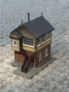
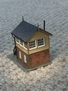
It has its limitations ( principally the coarse brickwork and lack of any interior detail ) but I was quite pleased with SJ, and perhaps surprisingly I learnt a couple of things in the course of making it which then came in handy for BID – more on that later. It only took a few weeks of intermittent modelling, and the project was helpful in “getting my eye back in”, and it boosted morale to have once more got the tools out and actually finished something.
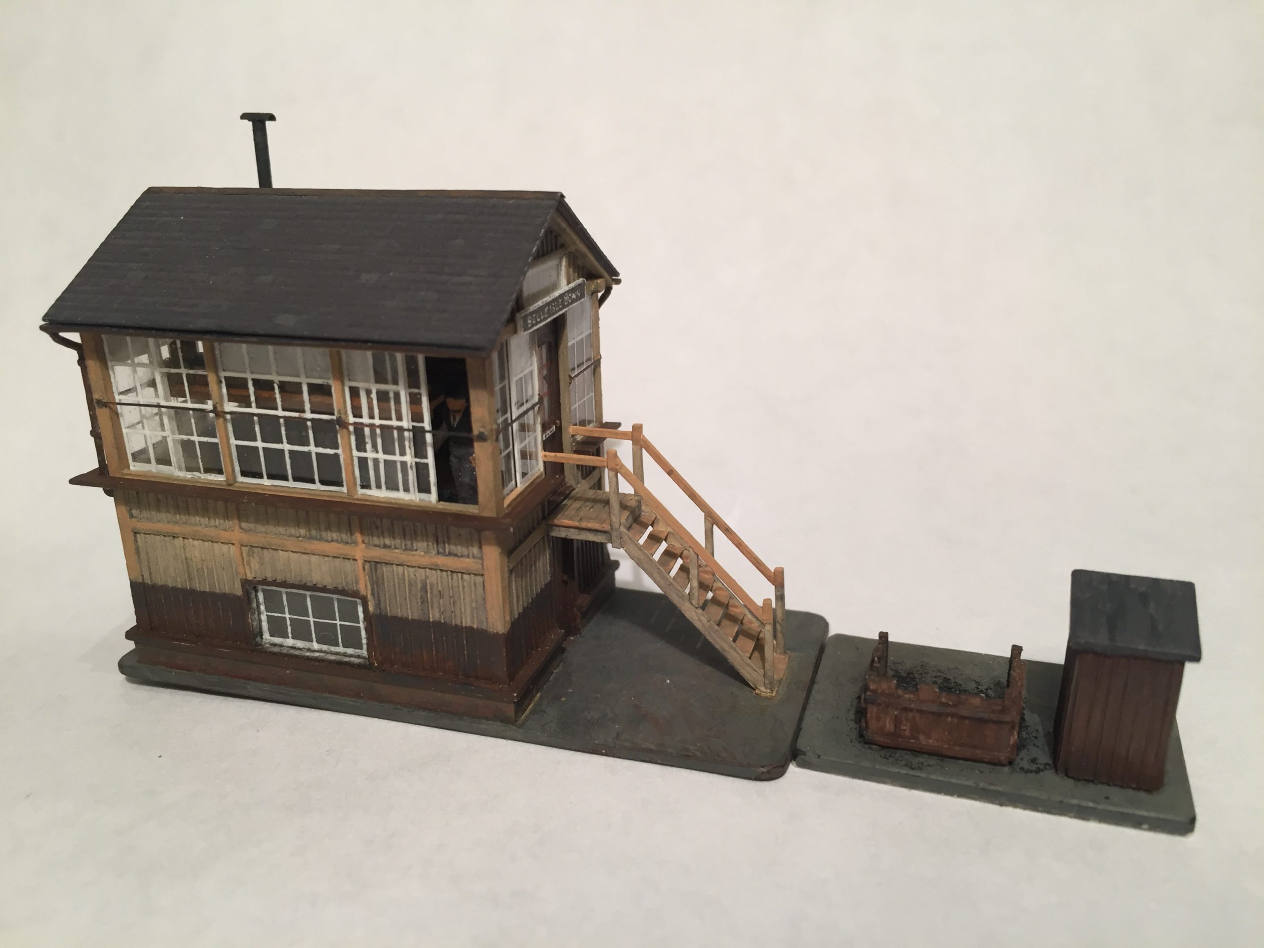
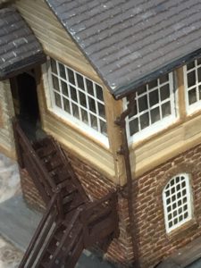
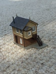
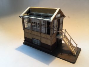
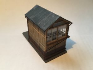
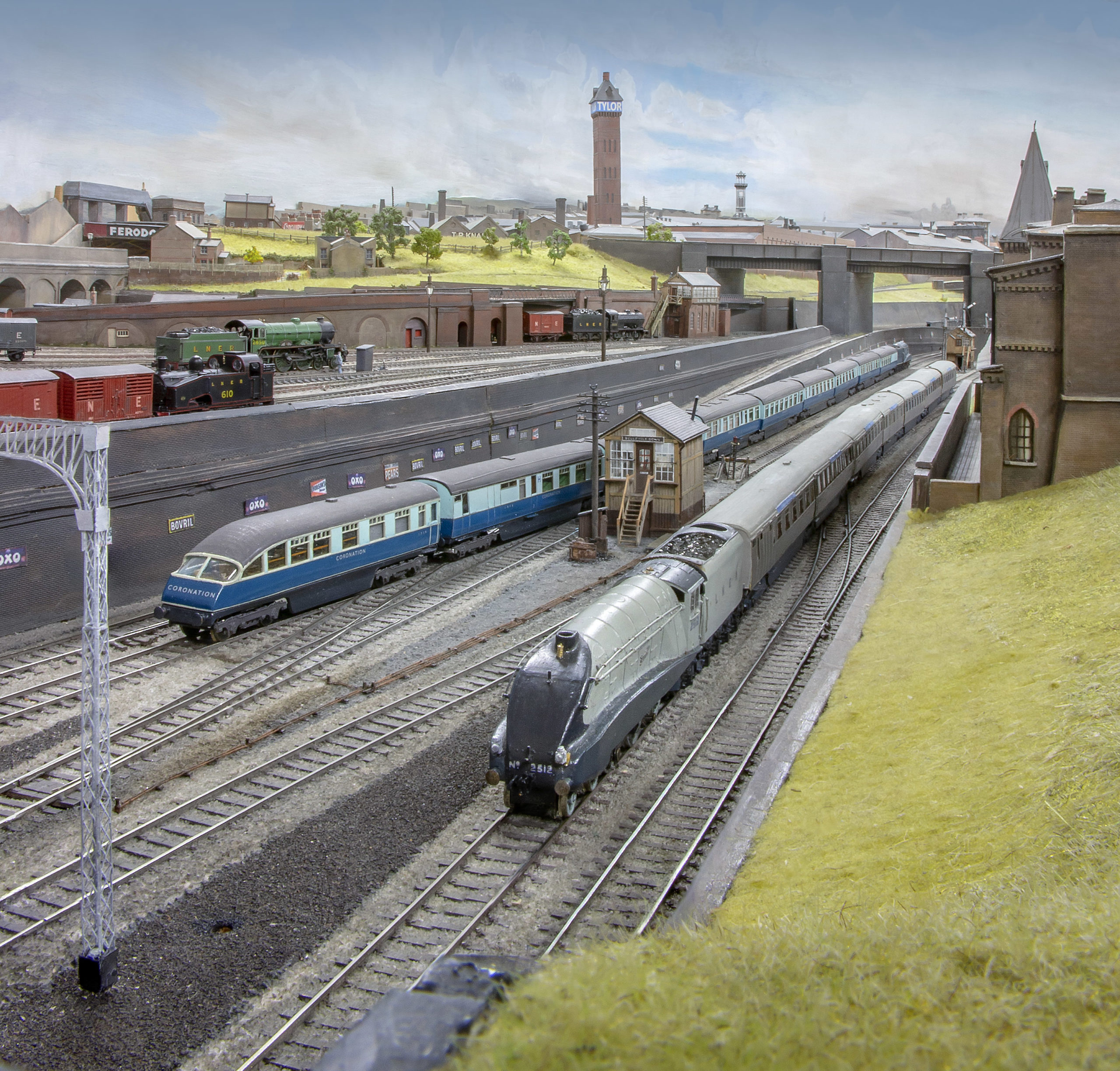
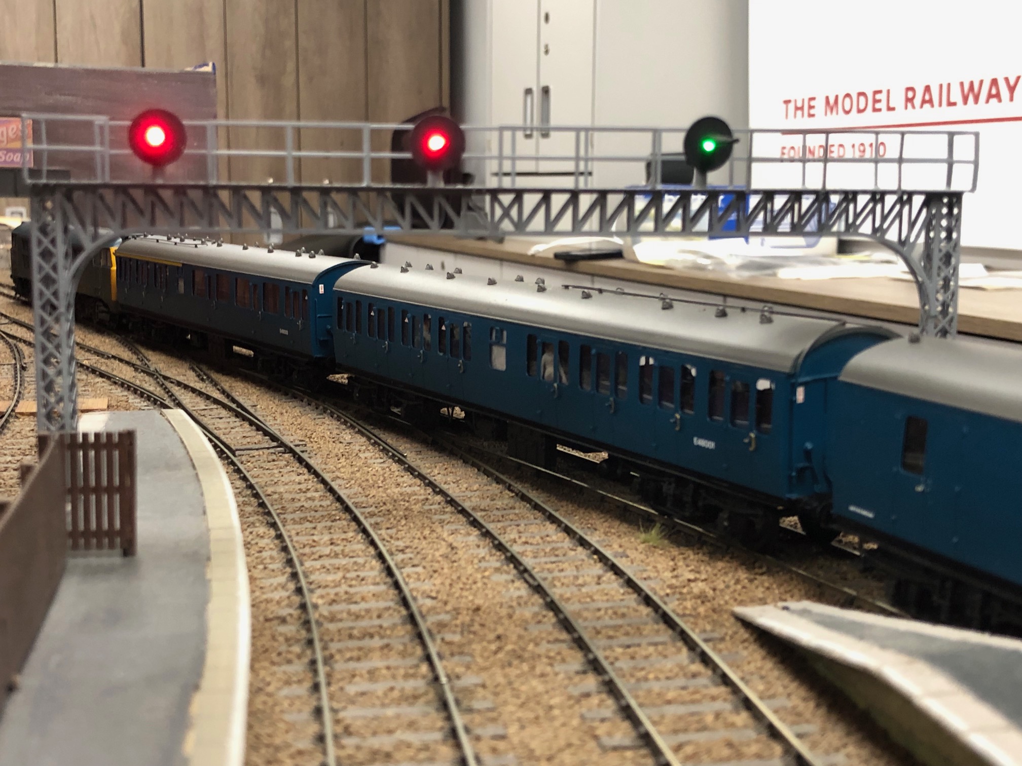
Fired with enthusiasm, I then started work on BID for real. Photos 2 and 3 show the finished model.

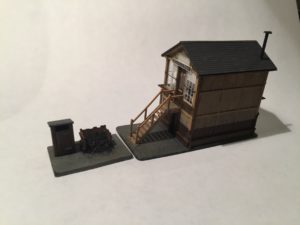
The real thing is a typical timber built box which comprises a timber framework infilled with wood panelling below, and doors and windows above. The model is made of styrene, the framework uses various different sizes of strip with sheet used for the panelling. The doors and windows are clear plastic, taped over the drawing so that the glazing bars can be drawn on in white drawing ink using a mapping pen and steel rule, bulked out where necessary with more plastic strip to represent intermediate framing.
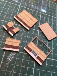
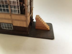
I started with the panelling. The real thing had vertical boarding, the joints covered with beading. To represent this I used Slaters’ 1mm planked sheet, with 10 thou plastic rod laid into the grooves. A bit tedious to do, but effective. The substantial posts at each corner were made from 60thou square strip butted to the ends of the panelling, the intermediate framing being represented by thin overlays on the panelling itself Photo 4.
Reinforcing panels were glued to the interior in the hope that they would counteract any warping – note the holes for getting solvent into the middle so the panels are not just secured at the edges Photo 5.
It was of course only after I had made all four panels with all the appliqued detail that I realised that when preparing the drawing I had underestimated the height of the box, and they were all too small ! So another cut and paste job on the drawing, and back to square one. I suppose it is character building….
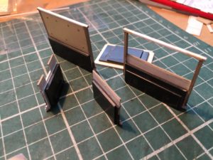
When the new sides and ends were done they were erected onto a base and the operating floor added Photo 6.
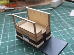
It never does any harm to make plasticard buildings as strong as possible, and the joints between the walls and the operating floor were well reinforced with offcuts of microstrip inserted from underneath via a hole in the base left for that very purpose. The floor and the interior of the back wall were covered with ordinary brown paper, which gives an even tone and suggests a wooden floor or internal paintwork more easily than painting, and also served to conceal the holes for the solvent.
Once the four sides were up it was possible to insert the top horizontal beams at the ends, creating the apertures for the glazing. The glazing was made to fit those spaces. First I fitted the sliding sashes ( which are glued behind the walls ) and then the fixed sashes ( which are in front of the sliding sashes and therefore fit between the beams ). Some of the window panes were “whitewashed” on the reverse, as seems to have been quite common on signal boxes.
Finally the door was added – a painted paper overlay on clear plastic, with glazing bars drawn in with brown ink, The door frame was built up onto the door from more microstrip once it was in place on the model. The fixed sashes were made a tight fit into the apertures, and then secured with PVA.
Meanwhile I had made the interior fittings, including an instrument shelf which was suspended from a false ceiling designed to slot in between the top beams Photos 7 and 8.
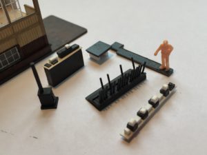
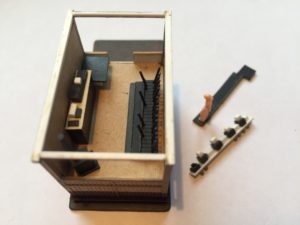
The lever frame was made from microstrip glued to holes in a piece of planked plasticard – the grooves made spacing the holes for the levers easier. The interior fittings are rather basic – the lever frame in particular is downright crude – but, as expected, once everything is assembled they are all but invisible, but do serve to block light in the right places which is what matters. The exception is the signalman who was deliberately placed behind an open window where he can be seen – I think his presence suggests a higher level of detail than is really there !
The interior and ceiling were fitted once all the glazing was in, because you need to keep the interior access clear while the glazing is fiddled into place. At that point I had what amounted to a little cube, waiting for a roof and the other exterior details. It was quite a relief to reach this stage because at last the structure was reasonably robust, and beginning to look like what it was supposed to be.
Next the triangular end pieces were made and fitted, complete with their windows and fascia boards, and stiffened by a longitudinal upright panel forming the roof ridge Photo 9.
I resisted the temptation to then add the roof itself, because the ridge piece served as a useful handle while the various exterior fittings were added. I did however make a temporary roof out of a folded piece of card laid in place, just to check that everything appeared in order.
So, on to the exterior details. The handrails are 10 thou plastic rod, simply glued in place and then touched in with black paint. The gutters and fascia boards are strips of plastic –the edges of the gutters are chamfered to suggest the semi-circular outline of the real thing. The downpipes are bent up from plastic rod, by trial and error, and mounted on fragments of strip glued to the framework. I don’t usually bother with any representation of the round mountings for the pipes, but in this case the prominent diagonal pipe at one end looked rather bare without them and I therefore added tiny fragments of Miliput to add some relief.
The staircase had to be made from scratch – the ready made Evergreen stairs were too narrow. This was an exercise in building out of microstrip “in thin air”, and the order of events was:
- Landing platform built out from first floor level; 2. Side rails for the staircase fastened top and bottom to the edge of the landing and the base; 3. Insert steps between side rails; 4. Add newel posts at top and bottom of stairs; 5. Insert handrails between newel posts; 6. Add intermediate vertical posts supporting handrails at mid point of staircase.
This looked daunting, but plastic card and strip is easy to trim to size so as to get a nice push fit between components, which can then be locked with a spot of solvent, and the structure gains rigidity as it is built up.
To space the stair treads evenly I made a jig, of sorts, out of slices of wooden coffee stirrer Photo 10.
The idea was that it would be tacked in place with a scrap of double-sided tape, the landing and siderails would be built around it, and then the jig would support, and space, the treads as they were added. Once all was done, the jig could then be removed by first pushing it inwards towards the end wall, and then extracting it sideways from under the finished staircase.
All went well until the jig came to be removed, when I found that solvent had leached through and in places the jig was itself now glued to the staircase. I had to use some violence to get it out, in the course of which several treads came away and indeed the whole staircase assembly itself had to be detached altogether. However, all was not lost as enough structural integrity remained for the wreckage to be reassembled with surprisingly little trouble – the landing was propped back into place and re-fixed with solvent, and I found that the missing treads could be added back by eye. To avoid this happening in future, I would try making the jig narrower than the treads, so that while it supports the treads it does not actually touch them where the solvent joint is made.
The window cleaning boards were added after the stairs. These were mounted, using Araldite, on little stubs of wire pre-glued into the sides before the sides were erected. It was beyond me to get them all exactly in line and at the same level, but not difficult to tweak them in situ so as to support the boards straight and level. On some signal boxes the boards can be fastened directly to the sides, which is obviously much easier, but on this one they can’t, not least because a drainpipe runs behind them at one corner and needs a gap to pass through. The boards should be supported by triangular metal brackets, but since the model will be viewed from behind, and looking down into a cutting, and the brackets would be more or less invisible under the boards, I decided I could get away with leaving them off.
I mentioned before that I had learnt a couple of things from the SJ rebuild. The first was to consider fitting windows from the outside onto ledges in the building side, rather than the more obvious fitting from the inside. This enables one to adjust the depth of the window reveal – obvious really – and is easily done using PVA ( which does not spoil the glazing ) rather than solvent to fasten the windows in place.
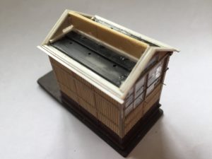
The second concerned the roof itself. One of the attractive features of the Skaledale model which made it worth improving was the roof which showed the slates in relief. Given BID’s position at the front of the layout, the roof was going to be its most obvious feature. Previously I had used scribed flat plastic card to represent slates, but I thought that in this case that might not be good enough. The plan I came up with was to use the 1mm planked plastic card, but to scrape each horizontal “plank” down at an angle with the edge of the scalpel blade, creating an overlapped effect like weatherboarding, and then to score in vertical joints to suggest individual slates. The scraping worked well, the grooves moulded in the plastic disappeared leaving an effect like shiplap timber. The vertical scoring process did result in ridged burrs which then had to be scraped back down, but the end result was ( to my eye anyway ) a more convincing roof with quite a subtle suggestion of overlapping slates.
The final touches were the stovepipe, and the name boards at each end. For the latter I made two large scale masters on black card, one drawn freehand in white ink, the other lettered with old white Letraset. The Letraset was in fact so old that it refused to rub off the carrier film, so I had to cut each letter out, film and all, and stick it to the card with double sided sellotape. The masters were then photocopied down to size. The Letraset one was not as bad as I expected, and in the end I couldn’t choose between them, so I used one of each.
To finish the scene, I made a privy and a coal bunker for the signalman on a separate base to be mounted at the foot of the stairs.
As can be seen from the photos, everything possible was painted as I went along, even if in places patches had to be later scraped clean again to allow subsequent parts to be glued on. This makes it easier to achieve clear demarcation lines, and for some parts which become inaccessible as the build goes on it is of course essential. Paints were largely water based, either acrylics or domestic emulsions. The model took about two months, from first cutting plastic to completion. To that needs to be added the time necessary to create the working drawing, and to peer at the drawing and photos to work out how it all fits together and how to make it. Time spent putting the job off not included !
Matthew Wald
The article first appeared in the 2mm Scale Association Magazine – which includes amongst its membership many MRC members. Find out more about the society and modelling in 2mmscale here
Find out more about Copengahen Fields here, and how to get involved and join the MRC here
You may also like...
Thursday Track Nights
We are open on Thursday evenings from 7pm to 9pm at our Keen House clubrooms. Visitors are welcome, please come along and introduce yourself.
Address:
Keen House, 4 Calshot Street, London, N1 9DA
Become a member