Controlling Electromagnetic Uncouplers
Graham Gilbert
20th February 2021
11 minutes
Electromagnet uncouplers are a proven method for uncoupling Sprat and Winkle and other couplings that require a magnetic “pull down”, but due to the heat generated by electromagnets when they are energised, there is the potential of heat damage to the baseboard or in the worst-case scenario fire, due to overheating caused by misuse or fault conditions. This article presents an electronic solution to overcome the common issues found when using electromagnets on a layout, based on the needs for our new EM gauge layout Orchard Wharf.
I originally wrote this article for inclusion in the Bulletin, but the level of detail perhaps makes this more suitable for a Blog where people can add comments and it be shared with a wider audience.
Two types of commercially available electromagnets were considered, the PK Mag by DG Couplings and the Dingham MK2 magnet. The performance of these two magnets was compared.
Both of these magnets were found to reliability uncouple the Sprat and Winkle and other magnetic “pull down” style couplings. Both electromagnets could be completely hidden by track ballast, however a wagon had to be precisely positioned over the electromagnet for reliable operation. By fitting a ferrous plate 25mm x 2mm placed below the rail sleepers the magnetic field could be expanded, the idea being a wagon could be uncoupled when positioned within ±15mm of the electromagnet. Ampere’s law which relates magnetic field to current and permeability states that for any closed path, the sum of the length element times the magnetic field in the direction of the length element is equal to the permeability multiplied by the electric current enclosed in the loop. This means that when the ferrous plate is added to the electromagnet a greater current is required to produce the same magnetic field at the point of interest, which was the wagon couplings.
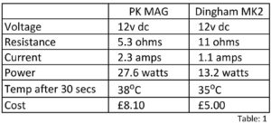
Table 1
From table 1 the Dingham MK2 electromagnet current requirement was 1.1 Amps. When the ferrous plate was fitted to this electromagnet due to the increased permeability the magnetic field was found to be insufficient to reliably operate the couplings. The PK Mag current requirement was 2.3 Amps, due to the higher power requirement when the ferrous plate was fitted the magnetic field was strong enough to reliably operate the couplings. Therefore, if it was desirable to expand the magnet field by adding a ferrous plate to increase the uncoupling range the PK Mag had to be used. It was decided that an expanded magnetic field would greatly assist and simplify the layout operation and the PK Mag fitted with a ferrous plate would be used. All future references to electromagnets in this article refer to the PK Mag fitted with a ferrous plate.
During discussions with other MRC members of their experiences with electromagnet uncouplers the following was discovered.
- Replacing pushbuttons on a regular basis. One member even stated that all the electromagnet pushbuttons had to be replaced after every two or three exhibition appearances.
- Warped baseboards due to the generated heat.
- Burning on the bottom of the Baseboard.
- Power Supplies failing due to excessive current draw.
Fire had not been a previous issue, but due to the heat generated under fault conditions this was considered a possibility that should not be ignored. Manufacture’s literature made it clear that these devices must only be used intermittently and they would get very hot, although the manufactures data did not to provide guidance of what was an intermittent duration and how hot was very hot.
It was decided to tackle the above issues one at a time to find a solution that allowed the layout to be operated safely. The solution needed to include the following criteria.
- Eliminate burning of the switch contacts.
- Ensure the electromagnet temperature did not exceed 100oC during normal operation and did not exceed 120oC at any time.
- Not to exceed the power supply current ratings.
An electronic circuit to supervise the electromagnet operation would be required to achieve the above, it was intended that the supervisory circuit could be operated from a pushbutton mounted on the side of the baseboard or in a control panel or have the capability to be operated from an electronic output from any commercial auxiliary control system for example Megapoints, MERG or a DCC interface. Pressing the pushbutton once would power the electromagnet for a timed period, thus allowing the operator to have two free hands to position the loco and wagons during the uncoupling operation.
Challenge 1: Replacing pushbuttons on a regular basis.
The first issue was the reported issue of replacing pushbuttons on a regular basis. The electromagnet manufacture’s data stated this could be due to carbon build up on the switch contacts. Inspection of a failed switch showed the problem to be burnt and pitted contacts rather than carbon deposits. To find the cause of the problem a test rig was constructed to stress the electromagnet using a 10 Amp relay switching at 30 Hz with a 3:1 duty cycle.
The results were observed with an oscilloscope which showed that when the voltage was removed from the coil, the electromagnet generated a negative 60v dc spike of approx. 5mS duration. See fig 1. The discharge current from the coil by ohms law was approximately 6.5 amps.
Electrical Signal when the electromagnet push button was released.
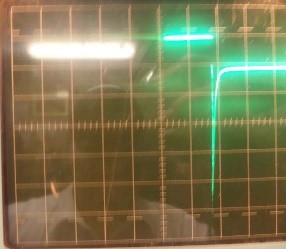
Fig: 1.
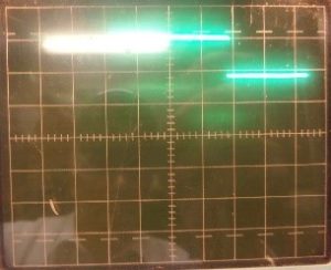
Fig: 2.
This explained the contact burning, but more worrying depending upon the switch quality the contacts could weld together permanently energising the electromagnet. This would result in an uncontrolled increase in temperature.
A normal panel pushbutton for model railways would be rated between one and six amp non-inductive load at 12v dc. Low-cost switches commonly use brass contacts that have a greater tendency to melt or weld together due to heat generated by the voltage spike. More expensive switches may have silver contacts that would be more robust, but being an inductive load, any mini pushbutton contact would eventually fail. Depending upon the switch quality contact bounce would compound the effect shown further shortening the contact life. The answer was to remove the spike using a flyback diode. Various diodes across the coil were tried. It was found that an IN400x series rectifier diode considerably suppressed the spike but did not completely eliminate it. Using a fast-acting SB5100 schottky diode produced the best results as shown in fig 2.
The problem of burning / welding switch contacts was solved, so we moved on to the next issue.
Challenge 2: Warped baseboards due to the generated heat.
To investigate this problem, it was necessary to have an idea of how much heat was produced, to this end a temperature gauge was clamped to the electromagnet coil and 12v dc applied. Figure 3 shows the temperature response.
The temperature shown is delta temperature degrees C (oC). This is the coil temperature minus the ambient temperature. Being an inductive load, as the temperature increases the coil resistance increases which reduces the power until the coil temperature reaches a state of equilibrium. Therefore, the temperature profile would produce a “S” curve corresponding to typical first order responses.
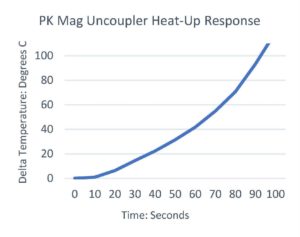
Fig: 3.
As can be seen from the graph the delta temperature at over 100oC is still rising and had not begun to stabilise, therefore it would not be unreasonable to expect the final temperature to be in excess of 300 – 400oC. This was worrying because the temperature from the core of the electromagnet is conducted to the top of the baseboard where cork and other flammable materials may be present. Experimentation using heat from different soldering irons found that 3mm cork started to turn black at around 175oC, became a black powder at around 350oC and ignited around 450oC. It could be seen that prolonged usage of the electromagnets would generate sufficient heat to damage a baseboard. To ensure the operator did not hold the button to operate the electromagnet for too long a circuit using a 555 timer in monostable configuration was developed to operate a relay for 20 seconds Fig 4. By including a coupling capacitor in the trigger circuit, the trigger button must be released and repressed to generate a repeat 20 second pulse. If less than 20 seconds was required to complete the uncoupling operation a cancel button could be pressed to deenergise the electromagnet to avoid excessive heat build-up. To avoid any interference from the electromagnets with other electronic circuits, the electromagnet power supply was completely isolated and floating from all other power supplies. A relay was used to switch the isolated power supply to the electromagnet. The relay used was a Songle SRA, this relay was selected because the relay contacts were made of Silver Cadmium Oxide (AgCdO), that decomposes and vaporises under the action of an arc, which results in a low welding tendency.
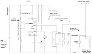
Fig: 4. Simplified uncoupler electronic circuit
To prevent the temperature of the electromagnet increasing outside the specified limits various options were considered. The obvious method seemed to be to directly measure the coil temperature. Measuring the temperature would require fixing a sensor to the coil. The concern was finding a fixing that could be easily removed to repair an electromagnet at an exhibition, but would be fixed securely (and in firm contact with the coil) enough not to work loose or fall off during transportation.
Secondly measuring a direct temperature did not take into account varying ambient temperatures therefore, for example if the room temperature was 30oC the temperature cut out would be reached significantly sooner than if the room temperature was 15oC, leading to a variation in operation availability.
Thirdly the intention was also to monitor for welded relay contacts. The majority of heat is generated from the core of the electromagnet, therefore when the current was removed the coil temperature would continue to increase resulting in a significant temperature overshoot. See Fig 6. Since the overshoot was a product of the core temperature, applied energy and time (the time current was applied), it was not desirable to measure the overshoot. (Fig 7 shows the different overshoot values between peak 1 and peak 2).
Fourthly temperature measurement is expensive and each electronics card may have required individual calibration with specialised equipment.
Temperature measurements of the coil showed the heating and cooling corresponded to a first order response curve, which was identical to the response of a resistor capacitor (RC) circuit. A RC pump circuit was developed where the characteristics of the coil and RC response were matched Fig 5. This provided an indirect temperature measurement that could be expressed generally as the capacitor charge voltage, where the coil temperature could be directly related to the capacitor voltage. As an accurate temperature measurement (within a few degrees) was not required, it was decided to use the indirect temperature measurement method.
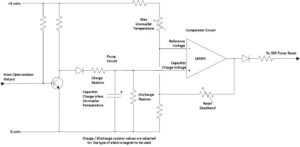
Fig: 5. Simplified Pump and Comparator Electronic Circuit.
This pump circuit was fed into a LM393 comparator, which reset the 555 monostable when an adjustable pre-set capacitor charge had been reached. Adjustable Feedback was added to the comparator to provide a dead-band, which allowed the electromagnet coil to cool by approximately 20oC before the electromagnet could be reused. LED drivers were added to provide indication at the operator’s panel when the uncoupler was in use and when it was cooling.
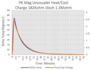
Fig: 6.
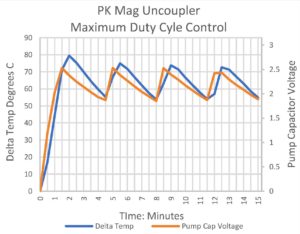
Fig: 7.
Fig 7 shows how the electronics controlled the electromagnet temperature when the device was force to operate in the worst-case scenario of a maximum duty cycle.
The problem of managing the generated heat had been solved so we moved on to the next issue.
Challenge 3: Burning on the bottom of the Baseboard.
Although under normal operation the magnetic uncouplers could be used safely, in the unlikely event of the circuit card relay contacts welding together the possibility of the coil temperature rising uncontrollably and the remote possibility of fire still existed. To solve this issue the LM393 consists of two comparators. The second comparator within the integrated circuit was connected to the RC pump circuit to trigger at a 20% higher capacitor voltage. A signal was then sent to open an external cut-out relay interlocked by a flipflop circuit that removed the 12v dc supply from the electromagnets. This would remove the power from all uncouplers connected to this relay until the faulty unit had been isolated and the flipflop manually reset. This may seem like an inconvenience, but damage to the electromagnet and the baseboard would be avoided.
This solved the issue of an uncontrollable temperature rise that would cause burning of the baseboard. Moving forward to the final issue.
Challenge 4: Power Supplies folding due to excessive current draw.
The final issue to be resolved was the potential current required if multiple electromagnets were operated at the same time.
Although it is improbable that all electromagnets on a layout would be energised at the same time a worst-case fault scenario needed to be considered, the potential maximum current drawn from the power supply would be potentially the number of uncouplers x 2.3 amps.
Excessive current draw could be due to either electronics failure or by mis-operation or multiple pushbuttons being pressed by accident or on purpose. It was proposed to operate all the electromagnets from a single 12v 5A power supply, this meant a maximum of 2 devices could safely be operated at one time. The operator panel pushbuttons were interlocked to only allow one device in a group of eight to be operated at any one time, thus maintaining the maximum current requirement to within the capabilities of the power supply even if mis-operated and multiple pushbuttons were pressed at once or in quick succession.
Current Development Status
Two protype circuit cards (mark 1 and mark 2) have been built on Vero board using through hole components, which is currently being beta tested on a MRC members layout (using a PK Mag electromagnet) to prove the circuit under operational conditions. All development testing was in free air, performance in an enclosed space under a baseboard is being evaluated, but to date no problems have been identified. The prototype is a single circuit. When the circuit has been proven, to reduce the physical size it is intended to provide two circuits on each circuit card, use surface mount components on bespoke PCBs. Development cost have been about £200.00 plus a lot of man hours. It is expected that the cost of the final built PCB will be approximately £6.00 – £8.00 per channel. The design has been developed in such a way that the circuit would be suitable for any type of electromagnets including Sprat and Winkle, Kadee, DG, B&B, Dingham, modified tension lock etc; with only the pump circuit charge / discharge resistor values requiring selection for the type of electromagnet used.
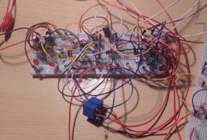
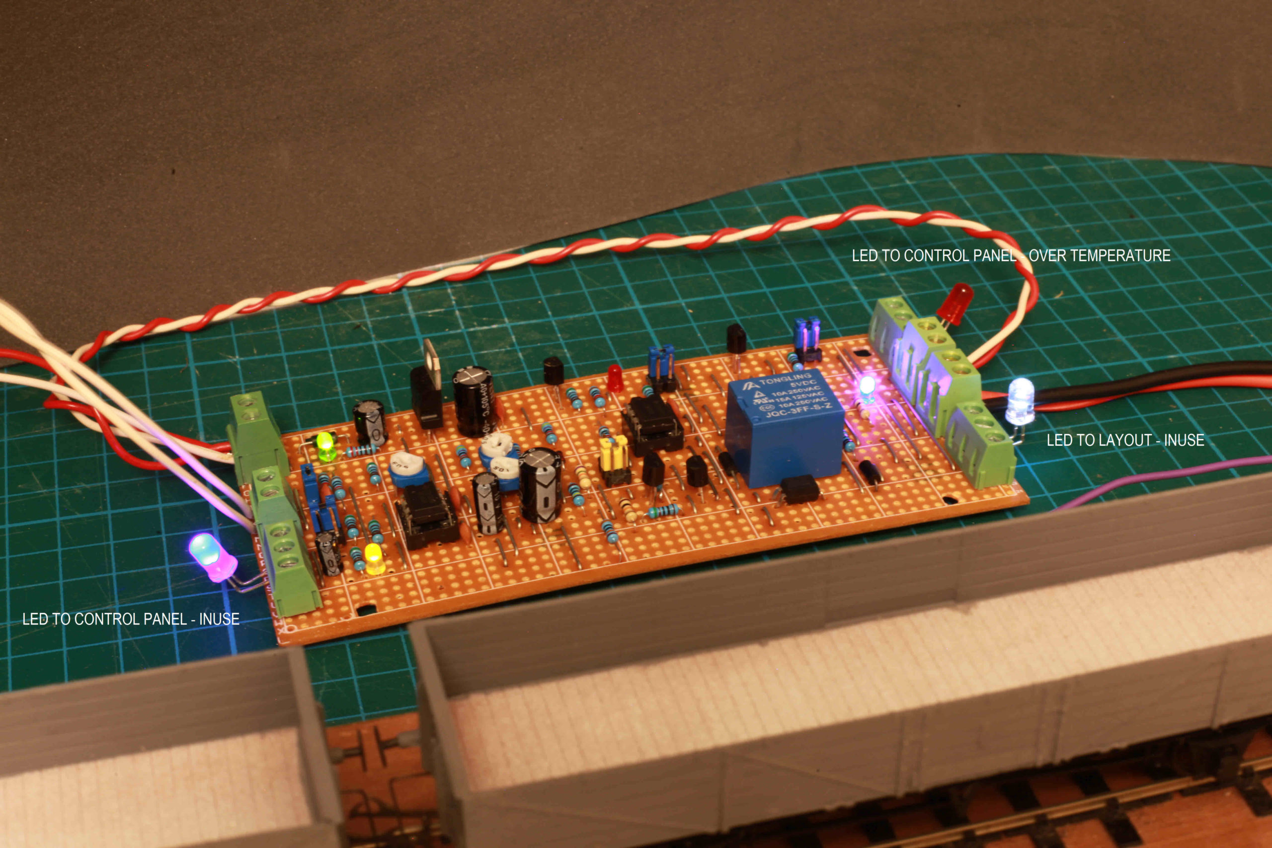
Fig: 8. The electronics under development
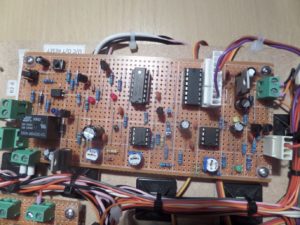
Fig: 9. The Prototype circuit
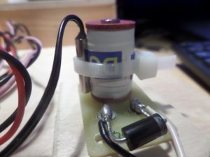
Fig:10. Electromagnet under the baseboard with Flyback diode and temperature probe used for testing
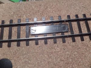
Fig: 11. Uncoupler plate mounted in the track.
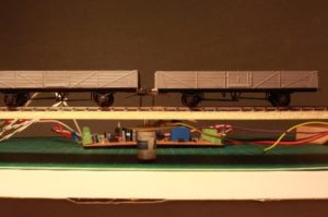
Fig: 12. Uncoupler Sequence De-energised
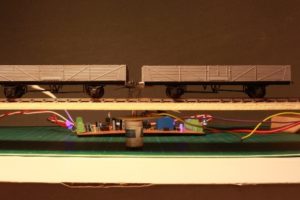
Fig: 13. Uncoupler Sequence Energised
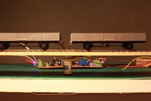
Fig: 14. Uncoupler Sequence Complete
Future Development
A possible future development of this circuit would be to redesign the circuit using a Peripheral Interface Controller (PIC). This would allow comprehensive diagnostics to be included, reduce the hardware complexity and eliminate the need to adjust the charge / discharge resistor values to match the type of electromagnet being used. The overall size of the printed circuit board (PCB) would also be considerably reduced.
Conclusions
Under normal operation of the layout when the uncoupling task takes a few seconds electromagnetic uncouplers are safe to use, but in the event of mis-operation or pushbutton failure they could potentially present a hazard that would damage the baseboard or in the worst-case scenario fire.
The described methods allow the electromagnetic uncouplers to be safely used without the operator needing to be concerned if a particular uncoupler has been over used and may be becoming too hot. Under normal operation the electronic supervisory circuits would not impose operation restrictions and if a device was overused and became too hot, a minimum cooling down time of around two minutes would be required. During this period a LED on the control panel would alert the operator that the electromagnetic uncoupler was cooling, maintain the safety of the layout.
Graham Gilbert CEng
3 thoughts on this post
Leave a Reply
You must be logged in to post a comment.
You may also like...

Thursday Track Nights
We are open on Thursday evenings from 7pm to 9pm at our Keen House clubrooms. Visitors are welcome, please come along and introduce yourself.
Address:
Keen House, 4 Calshot Street, London, N1 9DA
Become a member
Graham,
Many thanks for not submitting this as a Bulletin article. You are quite right that the blog is the better place for it.
Having said that, one thing missing is the total cost per uncoupler. I mention this, as the necessary protection measures look as though they could mount up to quite a sum.
For Orchard Wharf, I believe we have changed to permanent magnets mounted on servo-operated swinging mounts, which do not pose any temperature or current problems.
John
Great to read this, Graham.And glad those tube wagons could be of some service. I’d like to mention that this project was carried out as part of work on the Club’s Orchard Wharf layout https://www.themodelrailwayclub.org/layouts/orchard-wharf/ and that we have plenty more electronics to complete for that layout, not just for uncouplers but for turnout and signal operation. There’s a control panel to build and there are MERG CBus cards to program. If you are a member or planning to join and this sounds like your thing then get in touch! Ben
Very interesting. Not for our bulletin but I assume this would make a very interesting MERG Journal article!