Rydes Vale – the rewiring concludes
Simon Humphries
2nd April 2021
6 minutes

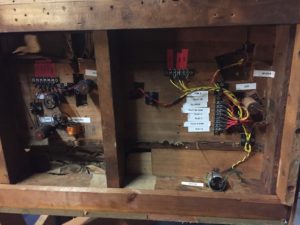
I have been busy under the boards of the Rydes Vale. After removing all the lineside accessories to protect them from damage and also allow easier access I have turned to the wiring. I have removed all the old wiring and am currently installing tag strips in place of the brass screws used as solder posts, this will make everything a lot neater underneath and allow for easy fault finding etc.
I have removed all the old spaghetti mess and the brass screws used to terminate the cables. I’ve kept the short lengths of cables connected to the track pins, not sure if you know but the method of track construction used was to solder deheaded nails to the underside of the rail at every sleeper or so per section, with each section being around 12″ in length, these nails are then soldered to with a length of wire running the length of the rail underneath the board, these lengths of wire are then soldered to at each end with multicore wire hence why you can see two wires for each terminal. I have tested every wire and rail length and all are still fully connected with the exception of a couple of rail length ends which I need to resolder.
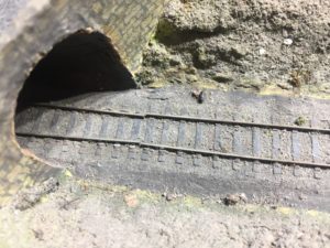
This shows how well this construction method holds up in the hostile environment it has endured in its life. A job lot of a 1000 or so nails were commissioned specially for the layout and I have a box full of these should I decide to follow this construction method on any possible extension I am considering in the future.
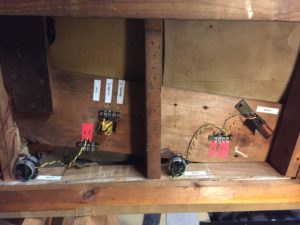
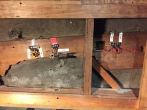
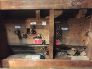
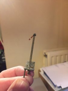
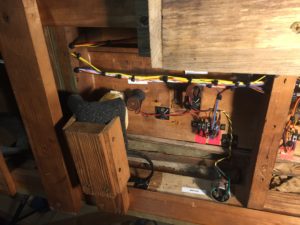
I have installed tag strips at each section and labelled accordingly. As you can see I have done the same for both track and lineside accessories and am starting to use coloured label for easy identification of both track and accessory. The plan is to run a separate loom for each, again I think this makes life easier later on. I have tested all the relays and with a bit of persuasion all are working well, these relays are used to operate the signals and have wires attached to the operating arms that push up a plate under the signal to operate, have removed the salvageable signal and you can see it is operating ok but needs attention (a job for later).
With thanks to Mark and his pointing me in the right direction I have managed to get all the Trix whistles working and have installed them in appropriate positions (Tunnel, tunnel entry, both ends of station). One thing that gets my goat is messy wiring and keeping it neat makes things a lot more pleasurable to work on especially when the inevitable faults crop up or you decide it’s time for a change for operational reasons.
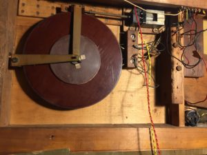
Other things I have done is remove the section and accessory switches, which is essential for the rewire and have made a new plate to mount the GPO switches as one had broken off. more on that later. Now I am turning my attention to the hidden train turntable at the end of the layout, actually I have got that working now as shown in this video:
And here are a couple of shots of the underside to show the drive
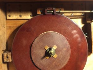
and a close up of the locking mechanism
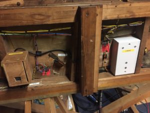
I had to complete the wiring to the existing switches as well as add a couple more items (in keeping with the original). I decided from the outset that the restoration will be entirely sympathetic with its age and, if at all possible, I will use all existing items including switches etc. The original section switches are ex GPO Strowger type open lever frame switches which are superbly built and very reliable, all 6 of these are still operating perfectly and showing negligible resistance on the contacts so were no problem to reuse, I had to fabricate a new housing for these switches as the original only held 4 switches and the other 2 were hanging off the edge.
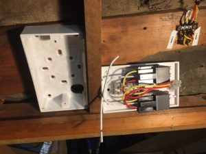
I also had another 2 ex GPO switches found in an old H&M controller Bert had modified, as these were of similar size and construction to the other switches, I decided to include them in the build in case of future need. The original switch box has now been repurposed with a new front panel to house the 2 DIN connections for Power and Controller, I have standardised on a 4 pin DIN connection to give power to the layout (12VDC for accessories, 16VAC for controller use only) and a 5 pin connection for the controller (currently using a Pentroller I got from Bert and performs well).
The micro switches used for accessory switches were less reliable and I found that 4 were non-functioning, fortunately they were easy to strip and clean so after a bit of TLC all are now working again. I also had another two spare switches which I have added to the build as I want some spares plus I need to do something different with the Ronson Shavers. Originally the layout had 4 micro switches dedicated to AJ uncoupler magnets although there were 6 magnets installed, also similar for the Trix whistles with 3 switches and 4 whistles.
I have decided to wire all accessories separately to maximise the flexibility, also not using the AJ’s yet I was unsure exactly what uncouplers we would use and also if we get a failure there are backups ready to use. Originally the micro switches were arrange in 3 banks and on the right bank the Ronson shavers were connected, these are positioned under the track bed and are able to vibrate the track if a loco gets stuck and yes they do actually work (albeit a bit noisy). The big problem is that you are physically able to get your fingers down behind the micro switches and it is 240VAC you are exposed to!!! Not wanting simply to remove the razors both myself and my 10 year old son Alexander both came up with two ideas that I have combined to produce something that I think is both safe and workable. After stripping the razors and making sure all worked well internally I tested in the bathroom (no I didn’t use one) and all worked perfectly so then it was time to come up with a solution.
Mechanical 240V switching in my opinion is not acceptable on an exhibition layout and Alexander said “Dad the shavers have a 110V switch so why don’t we use them on 110V surely that is safer?” “Good call Son great idea! I have a 110V auto-transformer unused in the garage too so that is what we will do”. I also invested in a couple of 12v relays and looked in the garage for a double socket housing and blank cover and I think we have now a workable solution that is safe and from the operator and spectator viewpoint is unnoticeable from what it was, photos in the dropbox link below.
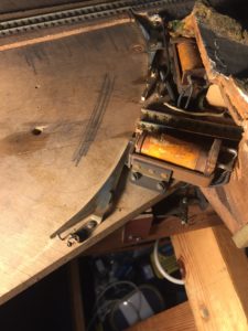
Once the wiring was complete I got up the confidence to look at the few unsecured rails that were floating around. Also had a point blade that had become unsoldered from its tie bar as well as a broken Omega loop. I was a dedicated Weller man when it came to soldering then I discovered Metcal at work a few years ago. That was one investment I was happy of here as it has definitely helped with delicate and accurate soldering. Time to move the Wellers on I think as I am now converted.
The wiring is now complete and below are links to the you tube video of progress as well as a link to the complete Rydes vale photo archive I have. If anyone has any photos of Rydes Vale I would welcome them please as there are a few things I can’t find on the photos I have
You may also like...

Thursday Track Nights
We are open on Thursday evenings from 7pm to 9pm at our Keen House clubrooms. Visitors are welcome, please come along and introduce yourself.
Address:
Keen House, 4 Calshot Street, London, N1 9DA
Become a member