Sarum Road – Part 3 – Assembly and the aftermath
Michael Joseph
28th May 2020
4 minutes

First Assembly
The boards went together without any major problems except one – I should have allowed an extra 1/8″ to for tidying up the edges of the board tops and in two cases I had to swap the tops for backscenes – more of them later. Also, I had forgotten to drill the holes at the base of the legs for the cord ties but apart from that there were no problems.
The Aftermath
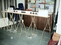
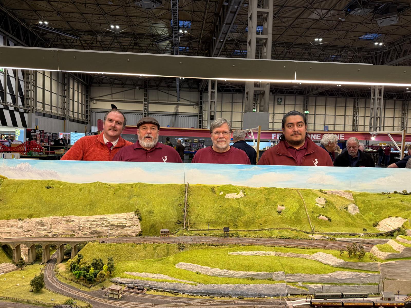
The boards were assembled for the first time at The MRC since there was plenty of free floor space. Setting up took just over 30 mins (no backscenes yet) and the first snag became apparent when although the layout was stable laterally, there was quite a sway along the longitudinal axis – that old parallelogram effect again! I didn’t have the materials to hand but I believe that it can be cured easily with a cord running from end to end, under the water bottles. (The layout is beginning more and more to resemble a WW1 aircraft!). In the photograph, on top of the boards are the card mock-ups. The overall height will be something over 4′ and with backscenes will be about 4′ 6″. Note the water bottles draped across the base of the legs for stability. Dismantling took about 20 mins.
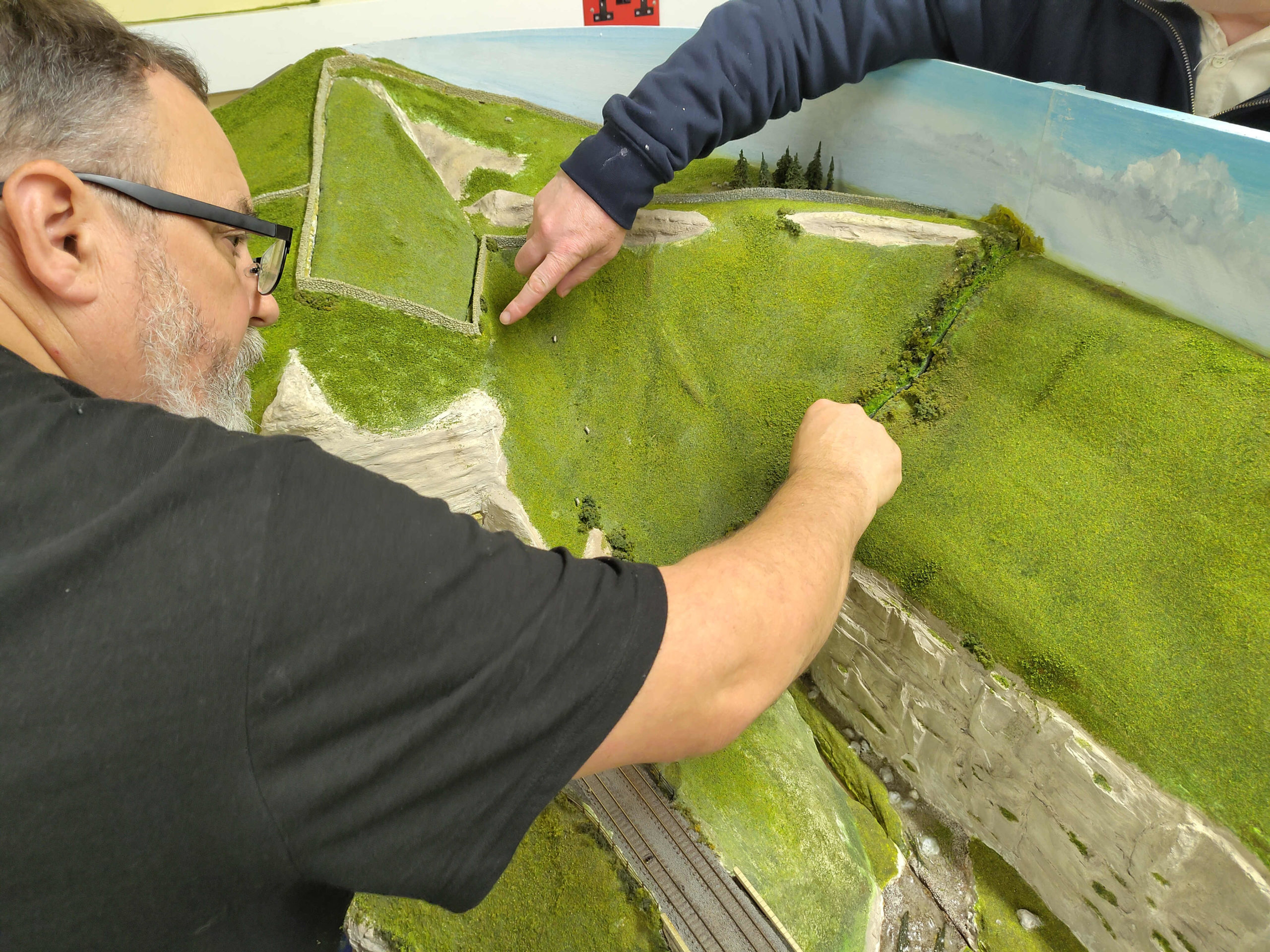
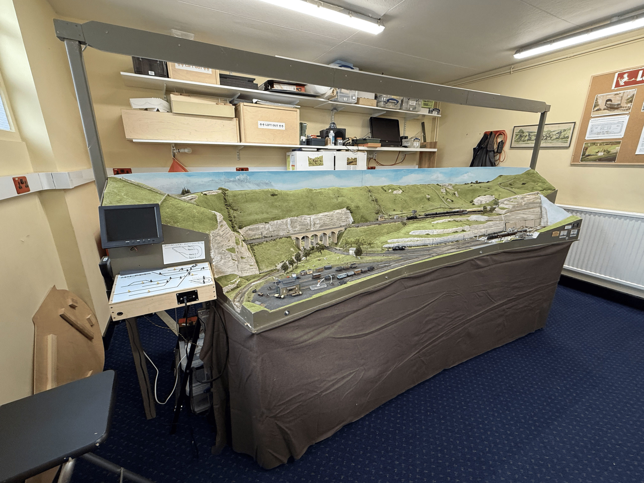
Here are the completed baseboards and legs:
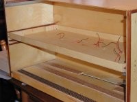
The box to store and transport the boards is turning out to be more complex than originally planned. If made up to 35″ long (the depth of the cubby hole), it could contain the large viaduct and bridge abutment structures as well. However, the box is much stronger than I thought it might be. A minor change to the box was caused by my eagerness in assembling the boards! I put the alignment dowels in and then later realised that I had not used the optimum layout making the two end boards (without dowels at one end) 0.25″ shorter than the two middle boards. Quelle chagrin! Note the runners to support the boards above and below the dowels to stop them moving about.
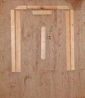
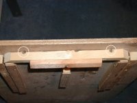
The next photo shows the jig used to assemble the boards and after having built four of boards it certainly proved that it was well worth the effort of about an hour’s work to make. The boards simply could not have been assembled as accurately without it. Also note the relieving holes in the view from the top; I had to use a small screwdriver to ease the boards out of the jig.
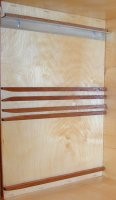
Control Panel
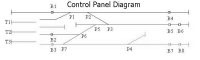
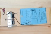
A track plan was drawn using MS Powerpoint, all pretty colours, etc. This was printed and mirrored on to the same piece of white card, cut to size and encapsulated twice to give it rigidity. Holes were cut for the switches and then the whole unit was mounted in a light wooden frame. The result is that the underside of the panel is labelled with a track plan so that wiring is made a lot easier. Simplified diagrams will also be attached to the underside of the boards.
Track Laying Commences
The cork underlay is self-adhesive flooring tiles stuck straight on to the top of the baseboards. The position for the cork trackbed was taken straight off the original card mock-up (remember that?). I had laid this when I found the hard way that the adhesive is not that good, so it will have to be gently prised up and relaid with Evostick. Originally I was going to use Peco code 75 until I realised that the rail is basically a flat bottomed profile instead of bullhead. After much thought I decided to get SMP rail (again code 75) and turnouts from Markway in Sheffield. I was not sure how this was going to work with the Seep point motors and bought an extra pair of turnouts to experiment with. I mounted a turnout and Seep onto a piece of board, the Seep angled at 90 deg. so that the operating arm would have enough ‘give’ to work the turnout because otherwise with the very thin boards there would be very little movement available. The Seep was only slightly modified by drilling an extra hole at one end to mount onto the aluminium bracket. Points, switches, wire etc all came from Junction 20 Models.
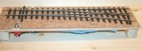
The actual track laying started with the two turnouts under the viaduct since the position of these determined the location of everything else. Droppers were added to the underside of the rails after marking the position of the pointwork on the cork and drilling a hole under the tie bar for the Seep actuating rod.
Sources of bits (usual disclaimers apply):
Markway, Sheffield Tel: 01142-449170
Junction 20 Models, Tel: 01923-270247 51, High Street, Kings Langley, Herts
You may also like...
Thursday Track Nights
We are open on Thursday evenings from 7pm to 9pm at our Keen House clubrooms. Visitors are welcome, please come along and introduce yourself.
Address:
Keen House, 4 Calshot Street, London, N1 9DA
Become a member