Sarum Road – Part 7 – Ballasting
Michael Joseph
25th June 2020
7 minutes
Scenery at last!
A bit of the third dimension comes to Sarum Road! But first the ballasting…
Oh well… Ballast Ballasting. What is there new to be said about it? Lengthy, tedious and boring are the usual but I had one of my bright ideas to make it quick and easy! Simple. Neat. Easy. And it didn’t work*.
Lengthy, tedious and boring it was to be…
Start with 2mm ballast – still a bit coarse and if I had realised just how coarse, I think I would have sieved sharp sand or something. Or written off a blender…
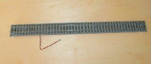
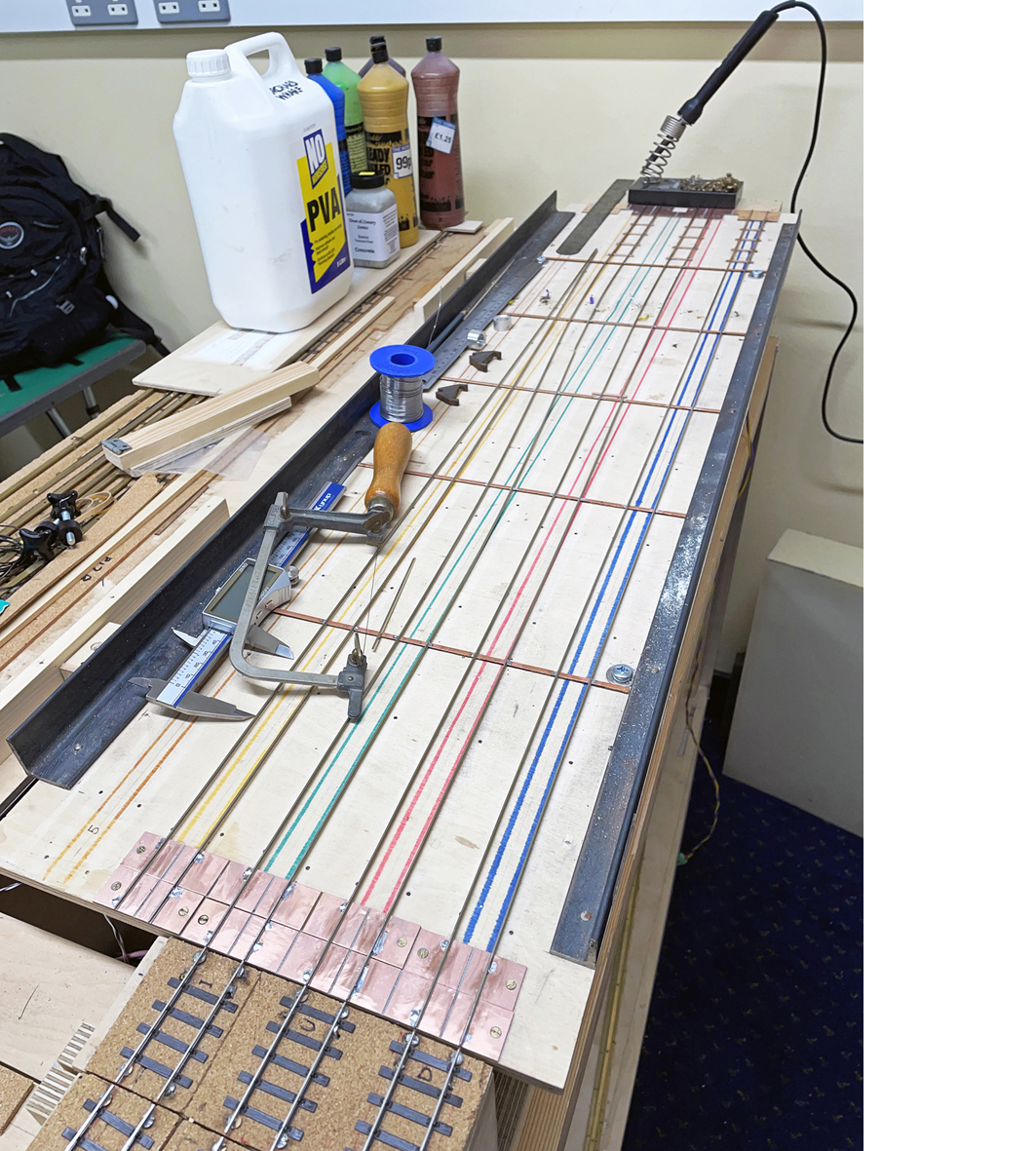
The ballast was laid around the sleepers with a small paintbrush used to brush excess chips away. The glue is a 50-50 mix of PVA and water (with a splash of detergent to get over the surface tension effects). I first used a syringe with a tapered and curved spout (Shesto) to drop the glue on to the ballast and later a disposable polythene pipette dropper courtesy of Tim Watson. It took a long time, even for only the nine feet or so of ballasted track – two evenings – with a large malt whisky for sanity (Highland Park).
To ballast up to the edge of the board I used strips of ply covered with aluminium foil clipped to the side and, of course, the pva did not stick to it. The idea worked fairly well. Finally, keep ballast well away from any moving parts, pointwork will never work again properly if it gets mixed up with ballast! Any glue that gets on to the top of the rail surface should be cleaned off with a damp cloth or if it dries with a track rubber.
The ballasting of the track in the loco yard was a little different. I wanted something resembling cinders*.
I mixed 50:50 water and PVA with a splash of detergent and then added polyfilla sufficient to make a thin slurry. Then some black water colour paint to make it grey and dribbled it on with the syringe (once I had opened up the nozzle a bit).
Done.
Oh, and then I realised I had got some on one of the point tie bars. Not clever and it took a bit of undoing. Don’t do it.
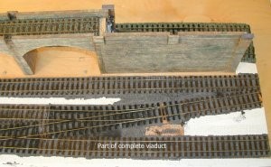
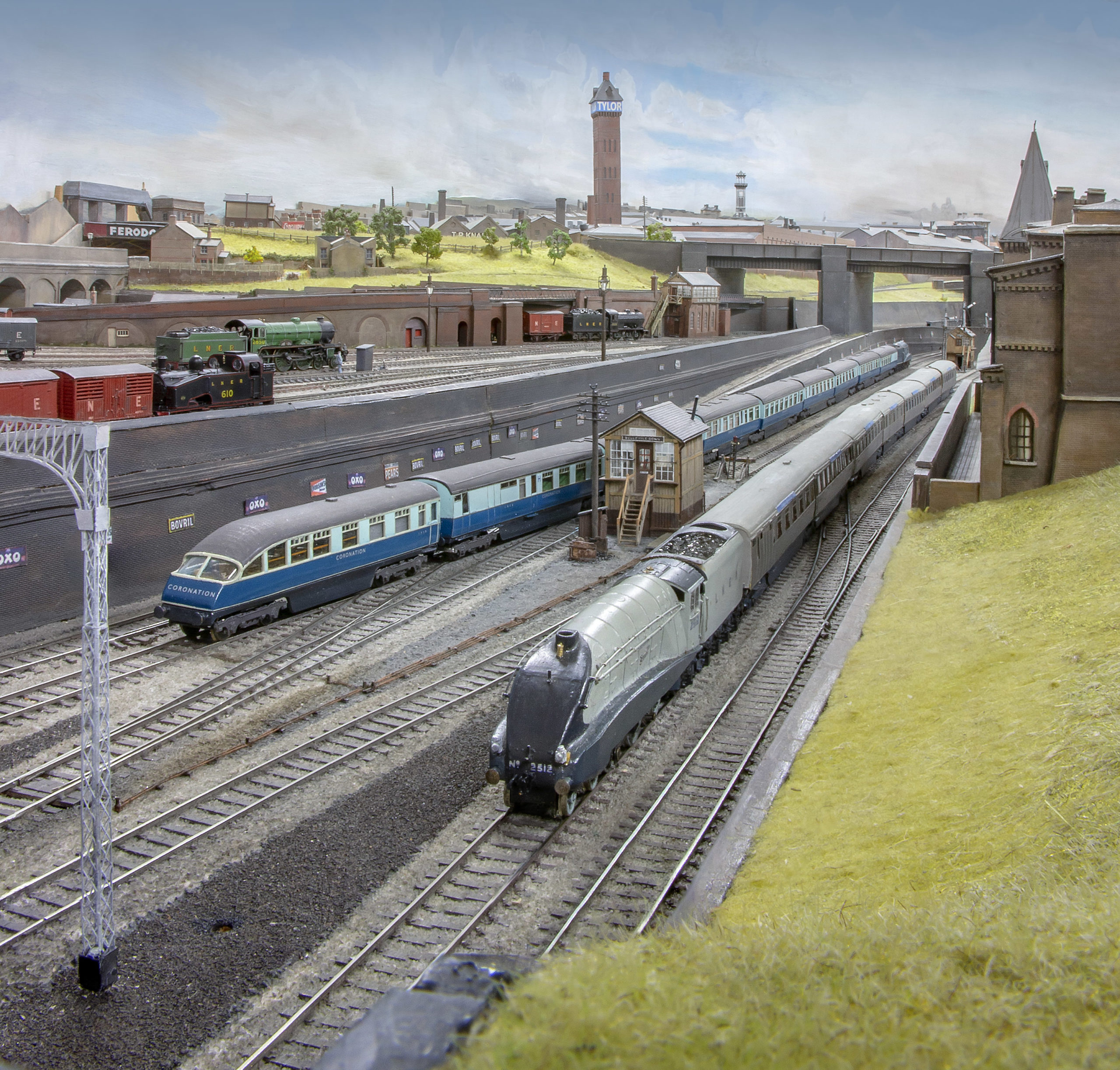
Well, it is not scenery so much as a viaduct, a long one…
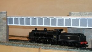
Running along the layout is nine foot of viaduct, with a bridge over the connection between the yard and running line. And I thought I was going to make this an easy and quick project!
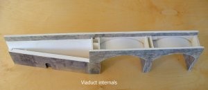
The viaduct was built using foam board (also known as Kappa board). It is used in the media trade for paste-ups and presentations and is usually thrown away, so if you have a contact in that line, use them! The sheets that I bought came from Carey’s in Watford in two thicknesses, ie 4 and 6mm. The 6mm was used for the side walls of the viaduct – just right for the nominal 18″ width of the parapet walls (supposedly a safety feature against carriages coming off the rails). The 4mm was used for the pier walls and to build up the structure. PVA was again the glue of choice.
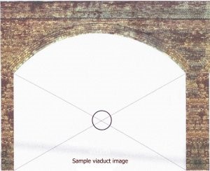
If the technology is available then I believe in using it! From the earliest days of the project I had wanted to print my own brickpaper, generated from photos of suitable samples. This means that it looks like brick, it can be scaled to the correct size, the arches are real arches and do not have to be ‘created’ with bits of curved brick paper, etc, etc. Finally, mortar pointing between the brick courses is only a quarter of an inch deep unless in very poor state and in 4mm scale is hardly likely to be noticeable from a typical viewing distance – it works out at 0.0033″ deep or 0.08mm: not something that I would lose sleep over!.
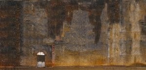
First, I started off with some photos of viaducts and underbridges in the Waterloo and Vauxhall areas. I went down early on Sunday mornings when there was no traffic and no-one to bother me(!) and took a load of photos of suitable structures. I was also lucky in that I was going down for work purposes one time and noticed that a particularly unpleasant underbridge had no lights working on one side – ideal! With Paintshop Pro on the PC I created a long strip of grotty brickwork from the underbridge. From a photo of most of one arch I developed a full arch with cut and paste, removed the perspective and then mirrored the image so that two arches just fitted on to an A4 sheet, they were also the right size for the base boards.
The viaduct image was copied, mirrored (to fit nicely on to A4) and slightly modified so that there were four similar but not identical images, especially to get over the ‘butterfly’ effect where I had mirrored images. One further image was created with repaired brickwork, ie bomb damage. These images were hacked further to generate the bridge abutment walls and then colour printed (100 gsm paper) on the PC printer. The inside of the viaduct parapet walls were cut from various prints that ‘went wrong’ and test runs. The viaduct underside and pier walls were sliced as needed from the grime ridden underpass image. (As an aside, this particular bit of road is truly most unpleasant and I saw very few pedestrians as a result…there are a series of bus stops here and no passengers – I wonder why?).
Having seen Ian Hopkins in action once, I bought some cans of ‘Photomount’ adhesive spray and a roller (all from Carey Stationers) along with the foam board. Do NOT use PVA unless you want beautifully curved viaducts – the paper shrinks!
From the Shesto stand at an exhibition, I bought a small plastic circle cutter that I modified slightly to cut the slightly larger radii of the arches. Next: cut out the arches, paste it all together and then discover that I had miscounted the arches! I made the same bit of viaduct three times before I got it right! The rest was easy. Extra detailing was added where needed by just sticking it on. The insides of the arches were created with card since the joints were not dead square/straight and the card disguised the problem. I made a couple of mistakes when doing these: the first was that I (without thinking properly) printed the inside of the arches on ordinary paper and laminated the sheets on to card whereas I should have printed direct onto card and the other was that I forgot to darken the area at the pitch of the arch before applying the brick papers so that there is sometimes a bit of a white line behind…
Oops. Brickpaper strips were applied to the inside parapet walls as well and in fact I used up the ‘mistakes’, cutting these into slices. Water colour pencils. I had never heard of them until I walked into Careys looking for some crayons to hide the ‘white line’ effect at the various paper and card joins. The pencils can be used as crayons, dampened slightly and paint ‘pasted’ on or used with a paintbrush or even a finger. I mostly used light and dark browns with a bit of yellow to hide the joins. They have worked very, very well.
Clamps were made with 4mm studding and soldered nuts (Apsley DIY again!) to hold the viaduct sections in place. A flat-U shaped piece of brass with nut soldered to it that grips the top of the pier walls. Only a couple per section are needed since the structures are light and strong. At the baseboard ends, the end walls were also covered with brickpaper – I experimented with black but it looked awful and just accentuated the break between the boards.
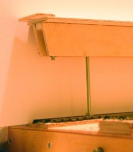
There are two bridge sections, one at the cross-over in the middle and the other over the traverser. Both have been built with the same technique. There is a basic ply structure for strength, in cross-section it resembles the Greek character P, (pi), overlaid with polystyrene. Structural sections (mostly ells and tees) in styrene from the Model Makers Resource have been added for detailing, especially the strengtheners. The main bridge is held in place at each end by 4mm studding that goes through the baseboards. These studding legs also hold it in place on one of the boards for transit. I had intended to make a removeable cosmetic styrene structure around the ply but found that Plasticweld had glued the styrene extremely solidly to the ply! Oh well, change the plan and weld all the styrene to the wood! There is also a third leg built in to store spare nuts and washers – just in case!
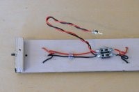
The track bed is more 3mm ply, laid on top of the foamboard and screwed in to mini wooden battens glued at intervals to the foamboard structure. Currently they are removeable. This means that I can ballast them without damaging the viaduct, wiring is easy and finally reed switches, etc can be fitted and adjusted to suit. The edges of the track beds were coloured with the watercolour pencils – with hindsight a spirit based wood stain would have been easier over the whole surface. As in earlier articles, the track was glued down, wired up and ballasted. Some neat little sliding connectors (All Components) were fitted to the underside so that the track bed and, more importantly, the viaducts can be detached easily. The brass screws that hold the track panels down have been blackened with gun blue.
* I tried mixing Cascamite, (a powder resin glue), with the ballast and then using a fine mist from a plant sprayer to wet it. The glue and ballast separated in spite of using detergent to get over the surface tension effects. TFW reckons it works but it didn’t really for me.
Suppliers
Foam board: Carey Stationers – 179-181 St Albans Road, Watford, Herts. Tel: 01923-236302
Studding: Apsley DIY, 38, London Road, Apsley, Hemel Hempstead, Herts. Tel: 01442-264793
Circle cutter: Shesto – http://www.shesto.co.uk
Connectors: All Components, PO Box 94, Hereford HR2 8YN Tel: 01981-540781
Plastic sections: Model Makers Resource – http://www.themodelmakersresource.co.uk/
PaintShop Pro – excellent software, well worth it for this type of work.
©The Model Railway Club.
You may also like...
Thursday Track Nights
We are open on Thursday evenings from 7pm to 9pm at our Keen House clubrooms. Visitors are welcome, please come along and introduce yourself.
Address:
Keen House, 4 Calshot Street, London, N1 9DA
Become a member