Stayin’ Alive
Tom Cunnington
5th September 2020
17 minutes
A closer look at improving running reliability in DCC using capacitors
A long-standing irritation in railway modelling is the tendency of powered model rail vehicles to stall owing to a momentary loss of electrical contact between wheel and rail. This is annoying in any circumstances, but is particularly problematic for sound fitted locomotives, exhibition layouts and when using computer control where the computer, unlike a human operator, is unable to bring to bear an over-scale hand to nudge the train along.
The ultimate solution to this is probably the use of “dead rail” technology: locomotives powered by batteries that can be recharged wirelessly at strategically placed points around the layout and that are controlled by Wi-Fi or similar. The technology for this exists, but is not yet mature. For those using conventional DCC, the solution to this problem lies in capacitors. Capacitors used in this way are usually referred to as “stay alive” or “keep alive” capacitors.
What are capacitors?
Capacitors are electronic components that, like a battery, store electrical energy. Unlike a battery, they can be charged in seconds and can be very small; but they store far less energy than a battery. However, they store sufficient energy to allow a model locomotive to overcome a momentary loss of electrical contact between wheel and track.
There are many different types of capacitors. Only some types are suitable for this application. Potentially suitable types are: (1) aluminium electrolytic capacitors; (2) manganese dioxide tantalum electrolytic capacitors; (3) polymer tantalum electrolytic capacitors and (4) supercapacitors.
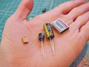
A selection of different types of capacitors, including two different values of tantalum capacitors, three different values of electrolytic capacitors and one pre-packaged super-capacitor bank
A new type of capacitor, the niobium electrolytic capacitor, has recently become available. These capacitors can tolerate a much higher voltage for any given size without exploding than aluminium or tantalum capacitors, but they currently do not store enough energy to be useful for model railways. However, when these become available in larger capacitance values, they will be ideal for this application.
For the purpose of this article, aluminium electrolytic capacitors will be referred to as electrolytic capacitors; manganese dioxide tantalum and polymer tantalum capacitors will be referred to as tantalum capacitors.
Electrolytic capacitors
These are the least expensive of the three. They are the physically the largest type of capacitor and thus store less energy per unit of volume than tantalum or super capacitors, but individual electrolytic capacitors are available in larger values than individual tantalum capacitors, so, where space permits, a single capacitor can be used rather than connecting many smaller value capacitors as is almost always needed with tantalum or supercapacitors.
Electrolytic capacitors have a reputation of a shorter lifespan than the other type of capacitors mentioned in this article. The lifespan of an electrolytic capacitor is dependent on how long its rubber seal takes to deteriorate and how long that its electrolyte (the chemical structure that stores the energy) takes to diffuse and become ineffective. Lifespan quoted by manufacturers varies from 1,000 to over 5,000 hours at 105oC, but for model railway use at up to approximately 30-35oC, a lifespan in excess of 130,000 hours can be expected, albeit with some diffusion of the electrolyte (meaning that the capacitor will gradually hold less energy as it ages). Manufacturers put an upper limit of 15 years on an electrolytic capacitor’s life(1).
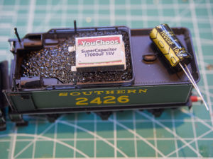
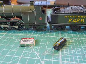
An electrolytic (right) and super capacitor pack (left) on top of the tender of an 00 gauge steam locomotive
Tantalum capacitors
There are two types of tantalum capacitors: polymer and manganese dioxide (MnO2) electrolyte. The polymer electrolyte is a viscous liquid that dries out over time. The manganese dioxide electrolyte is solid and has a practically unlimited life provided that the rated voltage be not exceeded.
Stay alive capacitors should ideally be manganese dioxide electrolyte types as these require less voltage derating than the polymer type, the significance of which is explained below. Capacitors under a model railway manufacturer brand name will normally be of the correct type. Tantalum capacitors come in significantly smaller sizes than electrolytic capacitors and where space is very limited, surface mount capacitors (i.e. those without built-in leads, intended to be soldered directly to printed circuit boards) can be used. These are even smaller and some may find it necessary to use eye magnification to solder them. Tantalum capacitors are more expensive than electrolytic capacitors, but not enormously so. These are especially useful for models with limited amounts of space, such as N gauge models. It is required to connect more than one of these capacitors in parallel to store enough energy to be useful in a motorised model, although a single such capacitor may suffice for carriage lighting to prevent flickering, as carriage lighting typically takes less than 1/10th of the current of a motorised model.
When capacitors are connected in parallel, the total amount of energy stored is the sum of that of the individual capacitors. Manufacturers only provide endurance values for these capacitors, which is typically 2,000 hours at 125oC at 2/3 of their rated voltage(2), but for model railway use at up to approximately 30-35oC, a lifespan in excess of 10-15 years can be expected(2). The difference between electrolytic and solid tantalum capacitors is that electrolytic capacitors slowly lose their capacity to store energy as the electrolyte defuses. Solid tantalum capacitors will suddenly stop working, becoming effectively open circuit (i.e. not storing any energy at all) at the end of their lifespan.
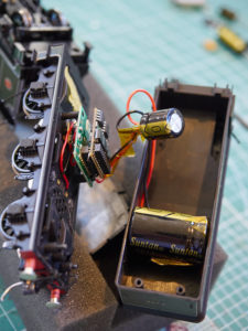
A pair of electrolytic capacitors and a DCC decoder fitted into the tender of an 00 gauge steam locomotive with tender body removed to see how they fit
Supercapacitors
These store the most amount of energy, but tend not to come in small sizes. These can keep 1:76 scale (00/EM/P4) locomotives going without external power for many seconds (potentially tens of seconds), to the extent that consideration needs to be given to the possibility of a run-away, on which more below.
Supercapacitors are low voltage devices: generally, they work at 2.7 or 5.5 volts, and need to be connected in series to be suitable for 16 or 25 volt use. When connected in series, the total amount of energy stored is less than that of any one of the individual capacitors, but the maximum safe voltage is the sum of the individual capacitors’ voltages ratings. The need to connect multiple individual capacitors together is why these types are larger in size than tantalum capacitors.
Pre-assembled supercapacitor packs for model railway use can be purchased from model railway suppliers. It is possible to put together a pack of super-capacitors from individual components, but, due to the high energy storage, specialist knowledge is required for this to ensure that the correct protection components be used correctly.
Manufacturers generally compare supercapacitors to batteries, therefore life expectancy is given in number of charge cycles, which is usually given as around 500,000 cycles(3) which is plenty for model railway use. These are the most expensive of the three.
Using capacitors in models
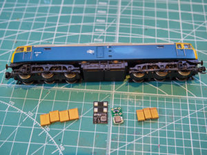
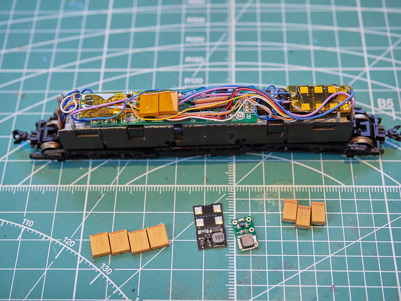
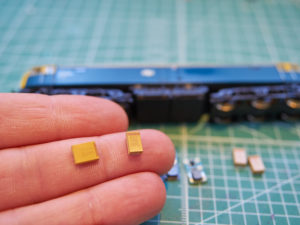
N gauge class 47 next to some surface mount tantalum capacitors and two different stay alive circuits
The basics
When an electrical voltage is applied to a capacitor that does not already have energy stored in it, the capacitor can draw a very large amount of current for a short time. This can cause problems, especially if multiple locomotives should be fitted with capacitors when the DCC current be turned on, and can be interpreted by a DCC command station as a short circuit(4). To prevent this, a charging circuit is required, which limits the rate at which the capacitor increases its charge, and therefore limits any current surges.
If the DCC track voltage should exceed the voltage rating of the stay alive capacitor (if the stay alive capacitor should be rated at 16v and the track voltage is more than 16v), it will also necessary to ensure that the charging circuit limit the amount of voltage reaching the capacitor. It is possible to make a charging circuit oneself, but commercial examples are available for ~£7 on printed circuit boards that make them much smaller than anything that most people could assemble at home.
Some DCC decoders have a built in charging circuit. If this is the case, this will be made clear in the decoder’s manual. In such a case, it is not necessary to have a separate, external charging circuit. In all other cases, it is necessary to use an external charging circuit when using stay alive capacitors. The external charging circuit is a separate component to the capacitors and needs to be connected between the capacitors and decoder.
Not all decoders are provided with connection points for an external charging circuit, and different decoders are not always consistent in how they should be connected, so it is important to check the decoder’s manual before proceeding.
The external charging circuit or capacitors, if the decoder has a charging circuit built in, need to be connected to the terminals or wires indicated in the decoder’s manual. If connection points (solder pads) for capacitors or a charging circuit be not provided, as in many Next18 decoders, a stay alive circuit cannot be fitted without soldering directly to the decoder’s or (preferably) the locomotive’s internal circuitry. For those who are not proficient in identifying precisely the correct place for connecting these components and soldering to a component not intended to be soldered in this way, or are not proficient to identify the correct gauge of wire for the maximum current draw of the model in question, there is a risk of serious damage to the decoder, locomotive or both.
A super capacitor and electrolytic capacitor at 25v next to an 00 gauge steam locomotive
The types of capacitors described above are polarised. This means that the positive and negative contacts/leads need to be connected to the external charging circuit or a decoder with built-in charging circuit the correct way around. Getting this wrong might cause damage and the capacitor could literally explode. Likewise, it is important to connect the external charging circuit (if used) to the decoder the right way around.
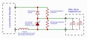
Loco Stay Alive circuit
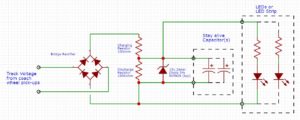
Coach Lighting Circuit
How much capacitance?
The amount of energy that a capacitor can store is called capacitance. It is measured in Farads (F). The amount of capacitance for stay alive use is typically measured in micro-Farads (µF). A micro-Farad is one millionth (1×10⁻⁶) of a Farad. 1,000μF is enough to supply the motor and lights for a few tenths of a second(4) and make a difference to the reliability of an N gauge locomotive, although ~2,000μF is better. For 1:76 scale models (00/EM/P4), more capacitance will probably be needed: 3,000 – 4,000μF should supply the motor and lights for a few seconds(4) and make a significant difference, depending on load, although more may be needed for locomotives fitted with sound or hauling a heavier load. The author of this article does not have experience in the larger scales (> 1:76), but inevitably more capacitance will be needed to make a difference. Of course, the larger the scale, the more space that is available for capacitors; but larger scale models also tend to be less prone to stalling in the first place.
In judging how much capacitance is enough, a reasonable (but very rough) rule of thumb is that, if a locomotive can carry on without power for 1-2 seconds at a slow speed, there is probably enough capacitance to prevent nearly all stalls. Even half a second should make a real difference.
Super capacitors can provide over one Farad of capacitance, but a typical commercial unit for model railway use will provide 6,800μF of capacitance in a rectangular package 20mm x 15mm x 5.8mm in size. This is unlikely to fit in any N gauge model, but will fit into larger 1:76 (00/EM/P4) models (e.g. into the tender of a steam outline locomotive) and should fit into most 1:43 (0/S7) models and above. For larger scales, larger supercapacitors are available. In 1:76 (and possibly even 1:43), this will give such a long running time as will let the locomotive run on for many seconds after cutting track power. This could cause a problem in some cases if the locomotive should be about to collide with something.
DCC emergency stop commands (e.g. the big red button on the NCE controller), which is actually a controlled stop, will send an E-stop DCC signal. On receiving this command, all commanded locomotives will immediately stop. However, if the locomotive with a super-capacitor should be on a piece of track that has become disconnected from the command station, e.g., by a faulty dropper, in the case of loss of power to a layout, if a conventional emergency stop button/switch that cuts track power should be pressed, it might run on for a number of seconds (possibly even > 10 seconds) before the energy runs out. Although the happening of a loss of power fault at just the same time as one needs to make an urgent emergency stop is probably rare, the possibility of this occurring and damaging a prized item of rolling stock might be a reason to be careful when using supercapacitors. Some DCC decoders intended for use with stay alive capacitors have an option to limit the amount of time spent running without a DCC signal to deal with this situation. It is recommended to make use of this feature if using any stay alive with enough capacitance to keep a locomotive running for a long time. Consult the relevant decoder’s manual for details on how to do this.
Stay alive capacitors are also useful in conjunction with carriage lighting to prevent flickering. The same principles apply here, and some manufacturers’ light bars have charging circuits built in. In the case of carriage lighting, less capacitance is required, as LEDs typically take less current than motors: about 1/10th of even an N gauge motor. A few hundred micro-Farads is likely to be enough for a carriage with lighting to a sensible level of brightness. To give an example, an N gauge Dapol light bar connected to 5x 470μF capacitors (2,350μF in total) will stay on ~5 seconds after being lifted from the track, which is far more than necessary to overcome flickering.
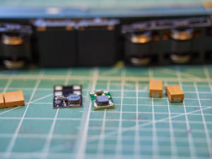
surface mount tantalum capacitors and two different stay alive circuits
What voltage rating capacitor? (A surprisingly difficult question)
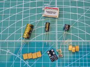
A selection of different types of capacitors, including two different values of tantalum capacitors, three different values of electrolytic capacitors and one pre-packaged super-capacitor bank
Capacitors have different voltage ratings. Supplying a capacitor with an overvoltage (more than its rated voltage) risks causing the capacitor to fail or even explode. An exploding capacitor inside a model locomotive body can do significant damage to the model.
To know what capacitor voltage rating to use, it is necessary to know the maximum voltage that may be applied to the capacitor. This will either be the track voltage or a voltage limited by the charging unit.
Measuring the DCC track voltage is slightly complicated. This is because the voltage is constantly changing from positive to negative: this is how it encodes the information that is sent to the trains. The easiest way of measuring DCC track voltage is to use a multi-meter on its AC setting. This is because AC is somewhat similar to DCC track voltage in that the voltage changes from positive to negative. However, it is not the same, AC changes more smoothly and slowly than a DCC signal. This means that a multi-meter set to AC will measure a voltage that is lower than the real voltage. This can (approximately) be compensated for by multiplying the measured voltage by 1.3. So, for example, if the multi-meter set to AC measures the track voltage as 10v, the approximate true voltage will be 13v (10v x 1.3 = 13v). Therefore, in this article the term “track voltage” refers to the voltage measured with a multi-meter on the AC volts range and the resultant measurement multiplied by 1.3. The track voltage can also be measured more precisely using an oscilloscope or a true RMS voltmeter, the latter of which are very expensive, but basic versions of the former of which can now be had relatively inexpensively.
Capacitors generally come only in a few set rated voltages, the most relevant for model railway purposes being 25v and 16v. The lower the capacitor’s rated voltage, the more energy that it can store for any given amount of size: lower voltage capacitors are physically smaller than higher voltage capacitors for the same amount of energy storage. Thus, for example, it is possible to get a 470μF tantalum capacitor in a 7mm x 6mm x 2mm size in a 16v rating, whereas the highest capacitance available in the same size at 25v is 220μF.
Running a capacitor continuously at its rated voltage will last for at least its warranty period; although this is commercially acceptable, it is not necessarily good practice. The maximum rated voltage is an absolute value and if this value should be exceeded, the capacitor will quickly fail or even explode. Capacitors must not be continuously subjected to their maximum voltage: if they should be so subjected, their life expectancy will be dramatically reduced. Opinion on an acceptable tolerance is diverse: some say to use a capacitor whose maximum voltage is 2 or 3 times the voltage that it will deal with continuously, however not exceeding 50%(8) – 65% of rated value is generally accepted.
Thus, to get the best lifespan out of a capacitor, the voltage from the charging circuit (or DCC decoder if directly connected to this) should not exceed 50%-65% of the rated value of the capacitor.
Many commercially available stay alive charging circuits are marketed as being suitable for use with 16v capacitors. The measured voltage output of one of these units varied between circa 12v and circa 14v DC depending on the track input voltage (circa 13v and circa 18v respectively). Why is this when the recommended rating for a capacitor that is continuously subjected to voltages >10.4v is 25v?
A fitter will say, “I don’t know how it works or if it is in specification, but I have been doing it for years and it always works or if there is an issue it was someone else’s fault”.
A technician will say, “I have measured the operating parameters, under normal conditions everything is in specification and it works O. K.. If it fails, I can fix it.”
An engineer will say, “I have calculated the normal and predicted fault parameters, under normal conditions everything is in specification and it works O.K.. Under fault conditions everything is in specification and damage will not occur, or under fault conditions the item exceeds specification and will be destroyed / will be safe / will cause consequential damage etc.”.
In the case of a commercial stay alive capacitor system, a typical design scenario would be that the product would be properly designed and engineered, but generally after a commercial risk analysis it would then be considered by the manufacturer to be not commercially viable, so a further analysis would be carried out to determine how to reduce production costs and maintain a commercially acceptable product.
Model railways are only expected to have intermittent use: therefore, in the case of capacitors, the operating margin could be reduced to maintain say a 10 year life expectancy (typical tantalum capacitor fail rates within specification are 7×10⁻⁴ / 1000hours at 50% of rated voltage. Maintained over-voltage fail rates in excess of 0.0125% are >68%. In excess of 50%, 100% fail. A capacitor voltage rating is not working voltage, but absolute maximum voltage). A DC voltage measurement from a typical commercially available charging unit was 14v, therefore a 14% voltage margin would give a minimum capacitor voltage rating of INT(14 x 1.14) = 16v, but with a reduced life expectancy, which would be commercially acceptable because of the intermittent use.
Under normal conditions, a current limiting charge resistor is all that is needed (if a resistor should fail it will go open circuit; failure is 1×10⁻⁴/1000 hours(6), which is an acceptable commercial risk). However, if the track voltage should exceed 16v, the capacitor may fail, so manufacturers usually fit a zener diode (that is a diode that clamps the voltage to prevent it from exceeding a certain value) and, to ensure that the capacitor remains within specification, use a 15v zener diode, which is the value used by most commercial charging units. If the higher track voltage causes the voltage to be clamped at 15v, the capacitor will not fail due to overvoltage, but its life expectancy will be reduced. If the capacitor starts to go “soft”, a slow deterioration of a few milliseconds of the charge will not be noticeable so this would be considered acceptable by manufacturers.
If the zener diode should fail open-circuit (i.e. not regulating the voltage) and the track voltage should be less than 16v, it would not matter as the capacitor would still be within tolerance. If the zener diode should fail giving a short circuit, it would not matter as the instantaneous current draw would either blow it open, stopping it from regulating the voltage, or trip the DCC (the zener diode failure rate is 2×10⁻⁵/1000 hours(7)). If the zener should fail and the track voltage were to exceed 16v, the capacitor would fail and possibly destroy the locomotive body. This is considered commercially acceptable as the probability of a zener diode failing and when the track voltage exceeds 16v is maybe 2×10⁻⁶/1000hours (DCC manufactures do not provide failure data) and the occasional £200 claim for a destroyed locomotive against the manufacturer can be absorbed by the profits and a willingness to pay compensation in such circumstances should mitigate any reputational harm caused by any damage caused to people’s models, so this is also considered acceptable.
For those who are not familiar with risk analysis, to try to give the above numbers a sense of proportion, the typical everyday risk of death from various causes are(5):
all causes of accidents (midlife including medical) 9 x 10⁻³ / 1000 hours
all accidents (per individual) 4 x 10⁻⁵ / 1000 hours
all accidents in the home 3 x 10⁻⁵ / 1000 hours
road traffic accidents 5 x 10⁻⁶ / 1000 hours
natural disasters (per individual) 2 x 10⁻⁷ / 1000 hours.
The design and specification process is done scientifically by assigning each component in the circuit and other commercial factors with a numerical weighting (as shown above) and crunching the numbers into an algorithm to determine the financial risk and commercial viability. A club member worked in industry in which commercial risk was assessed in a similar manner.
So, should modellers use 16v or 25v capacitors? Under normal conditions, using the correct charging unit, 16v capacitors are probably fine; they are definitely commercially acceptable (as described above). Under certain very rare fault conditions, 16v capacitors could cause terminal damage to the locomotive’s body. Some might take the view that the higher energy storage of 16v capacitors in a given space outweighs the possibility of the remote risks – and these are remote risks – but exploding stay alive capacitors have been known to happen as a search of popular model railway online forums will reveal. The author of this article has experienced an exploding stay alive capacitor himself (in circumstances of >16v track voltage), although fortunately no damage was done, as the locomotive body was off the chassis for testing at the time.
From the rough and ready analysis data above, there is more chance of a fatal accident in the home than any one capacitor exploding as a result of a simultaneous failure of the voltage limiting zener diode and track voltage exceeding 16v, but even so, one would expect there to be dozens of incidents of capacitor failures caused this way every year in the U.K. and far more again in circumstances where overvoltage protection has (unwisely) not been used, and this does not take into account the possibility of explosions caused by user error (e.g. inadvertently connecting together the input and output of the charging circuit when soldering, bypassing the protections). Therefore, even when proper overvoltage protection from a good commercial charging unit is being used, it is preferable to use 25v capacitors wherever there be space to do so inside a locomotive’s body.
There is one case, however, when it is definitely necessary to use 25v capacitors regardless of the space available in the locomotive body. This is where there the charging circuit does not limit the voltage so that the capacitor can receive the full track voltage. Since DCC track voltage can get as high as 20v in some cases, the rated voltage of the 16v capacitors could be exceeded, and 25v capacitors should always be used in this case. In these cases, reputable manufacturers will normally explicitly recommend 25v capacitors(4). This recommendation should always be followed. Some inexpensive (<£5) stay alive charging circuits for carriage lighting purposes might not have overvoltage protection or contain a proper warning against the use of 16v capacitors, so it is wise to use 25v capacitors when using charging circuits of an unknown brand. For carriage lighting, the amount of energy that can be stored is less critical, so using 25v capacitors should be less of a problem.
Conclusion
The use of stay alive capacitors can greatly enhance the reliability of model railways. They do not obviate the need for regular track and wheel cleaning nor of well laid track and reliable wiring (not least because a locomotive will not respond to control if there be not an electrical connection to the command station), but it is not usually practical to keep every millimetre of rail completely clean at all times, not least because the passage of trains over the track itself can cause dirt and oxidisation to accumulate, and thus stay alive capacitors can prevent irritating (and, if exhibiting, embarrassing) stalls which might otherwise occur despite one’s best efforts.
Stay alive capacitors are likely to be especially useful for locomotives with a small number of pick-up points, such an 0-4-0 industrial shunting engine. For such locomotives, reliable running without a stay alive can generally only be achieved with perfect track and a fully compensated chassis, and making such chassis is very taxing in scales smaller than 1:43 (0/S7) (or perhaps 1:64 (S)). The lack of compensation combined with the lighter weight of such locomotives means that the slightest irregularity in track will cause a loss of contact on one side or the other which can be overcome with the use of stay alive capacitors.
It is an unfortunate irony of stay alive capacitors that the locomotives that most need them (those in the smaller scales and those with fewer pick-up wheels) tend to be those with the least space to accommodate them. It is perhaps then not surprising that the decision as to whether to use 16v or 25v capacitors can often be a difficult one.
James E. Petts, with technical assistance from Graham Gilbert
James and Graham are MRC members, and part of the Orchard Wharf group. James is also building a substantial finescale N gauge layout
References:
- led-professional.com/resources-1/articles/concepts-to-overcome-lifetime-issues-of-led-drivers
- KEMET 491 series datasheet.
- VinaTech EDLC 10F supercapacitor datasheet
- Zimo decoder instruction manual 210-03-01 P50
- Functional Safety – D. J. Smith & K. G. L. Simpson
- Defined by the colour coded 5th resistor band
- ROHM quality assurance and reliability diodes
- AVX high reliability solid tantalum capacitors – B. Fairey
You may also like...
Thursday Track Nights
We are open on Thursday evenings from 7pm to 9pm at our Keen House clubrooms. Visitors are welcome, please come along and introduce yourself.
Address:
Keen House, 4 Calshot Street, London, N1 9DA
Become a member