DCC installation – 4mm scale Heljan Class 15
James Petts
28th March 2021
5 minutes
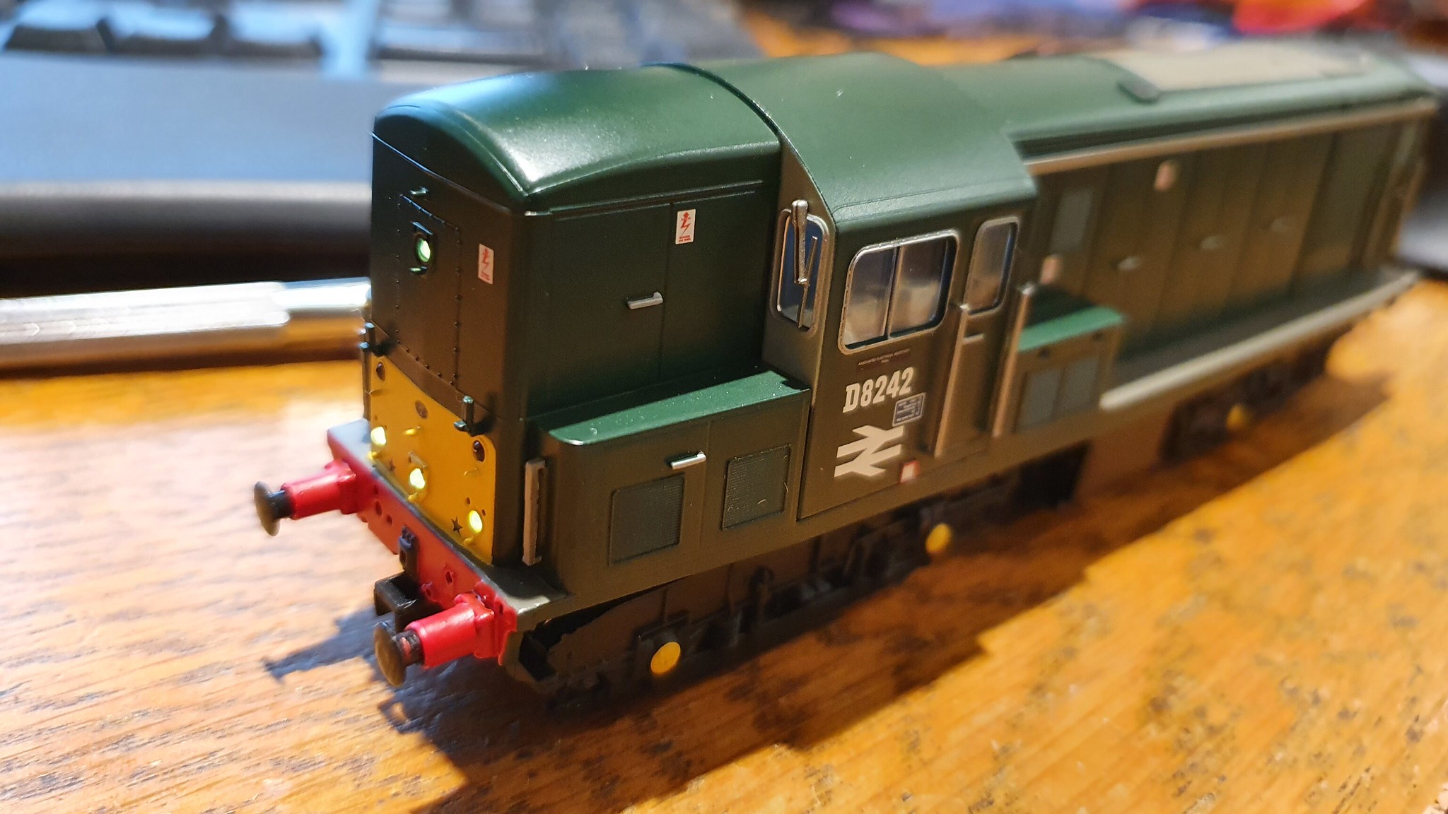
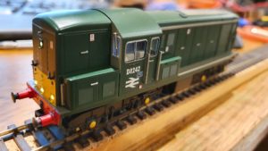
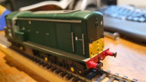
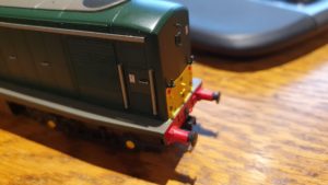
I have been DCC fitting one of the Heljan class 15s that arrived to-day and that I had ordered for our late 1960s period Orchard Wharf, locomotive D8242, as depicted in real life here and here.
Photographs of the finished article can be seen above and here:
I have made some modifications to the wiring of this locomotive to allow the front and rear lights to be controlled independently, as well as configuring this to work with the uncoupling release by pressing the F2 which I use on my N gauge stock. I’ve also fitted a 6,800µF stay-alive capacitor.
I thought that it might be helpful to document what I have done here. First of all, the decoder: I have used the Zimo MX633R (which I notice are currently hard to find; I have no spares of these, so will not be able to fit the other locomotives for a while it seems). The slightly cheaper but slightly larger Zimo MX635R would be equally suitable (and these instructions would equally apply), as there is ample space inside the body (unlike the N gauge models with which I am more familiar), but these are also difficult to find.
Secondly, body removal: this is very difficult with this model as those who have already fitted one will attest. I found this video from Jennifer Kirk useful in understanding the pitfalls, as the instructions are not clear, although I recommend avoiding prising with a screwdriver if at all possible (and doing so gently if unavoidable).
Thirdly, the stay alive. I use the YouChoos 6,800µF supercapacitor. One can also get an even higher capacitance model, but this is more expensive and 6,800µF is more than ample for a 1:76 scale model (at least with a modern motor; perhaps a whitemetal kit with an X04 motor would be another matter). Fitting this is straightforward: just solder the loose blue wire from the decoder to the single copper coloured leg and solder the loose grey wire to one of the other two legs. Then – and this is important – wrap the whole thing in Kapton tape, as the whole exterior casing is connected to negative. There should be space inside the body for this, but there is not enough space on top of the decoder. I have put this at the no. 1 end (far from the cab) in my model, where there is a good amount of space.
See here for a photograph showing the stay-alive in action: you will note that the locomotive is on my workbench with its lights still fully illuminated from having been on the track a few seconds ago. See
showing the locomotive running alone the track, being removed from the track, then continuing to run along the workbench for a second or two. This level of capacitance should prevent stalling on all but the most extreme levels of oxidisation of the track even at ultra-low speeds over points.
Fourth, the lighting. Unlike with my N gauge models, this does not require any soldering to pads on the decoder, so is easy. Unsolder the “R” (not the T-R) and “W” wires from the no. 2 (cab) end of the PCB. These connect to the red and white rear (no. 2 end) LEDs respectively. Solder these instead to the brown and green wires coming from the decoder. Note that it will be necessary to cut the green wire going to one of the pins on the decoder. This pin is not used on the model, so the wire needs to be cut in order to use this function output. Connect the green (function output 1/FO1) to the wire disconnected from the “W” and the brown (function output/FO2) to the wire disconnected from the “R”. (If you get these the wrong way around, you can just change the CV settings accordingly). Make sure that the joins are insulated with heatshrink, insulating tape or similar.
Note that you do not need to add resistors for this model as 10k surface mount resistors are already built into the LED circuitry at the ends of the model, but adding resistors may be necessary in some other models where the resistors are on the main PCB (this needs careful testing on a per model basis so as to avoid blowing the LEDs; blown LEDs can be replaced, but this is difficult as they are surface mount components).
After this, the model can be reassembled; then comes the CV configuration. I have put together a spreadsheet showing all the various settings that I have used: see here. This is an adapted version of a spreadsheet that I have used for my home layout and found very effective when programming lots of similar locomotives. The spreadsheet assumes the use of JMRI DecoderPro, which is by far the easiest way of configuring DCC settings.
These settings combined with the above rewiring mean that the following function keys have the following effect:
F0: directional head/tail lights (the default behaviour);
F9: turn off tail lights; and
F2: release tension in coupling and pull away (press and hold – use this over active uncouplers).
I could have configured F3 to turn off the headlights, but that is not likely to be a useful setting in all but very rare cases. I’ve not added cab lights as there is no cab detail in this model. I have made the lights about 1/8th as bright as they are by default, as Heljan seem to like making these LEDs very bright indeed.
I have adapted the speed settings so as to cap the maximum speed: this compresses the 128 speed steps into the range of available speeds and thus gives finer control. As I do not currently have an 00 gauge layout (I have not converted this to EM yet – I am awaiting the Ultrascale wheels that I have ordered, which are likely to take a considerable time to arrive), I cannot use TrainController to test whether the maximum speed in the decoder is in fact close to the maximum speed at which these locomotives were permitted to travel (60 m.p.h.), but my very approximate by eye guess is that the current maximum speed is closer than that which obtained by default.
Also, I have enabled DC running on this model to enable it to run on Tom’s “Minories” layout when it has been EM converted. I have also retained the NEM coupling pockets to allow fitting Kadee couplings for this purpose. When running on DC, it is set to assume that F0 and F9 are both on, giving directional headlights but no directional tail lights, as suitable when hauling a train.
Although this documentation is specific to the Zimo decoders, I believe that something similar can be achieved with most decent decoders such as Lenz and ESU, although I am not entirely sure whether all of this is possible with any given other decoder brand. However, how to achieve these things may be subtly different for different types of decoder.
You may also like...
Thursday Track Nights
We are open on Thursday evenings from 7pm to 9pm at our Keen House clubrooms. Visitors are welcome, please come along and introduce yourself.
Address:
Keen House, 4 Calshot Street, London, N1 9DA
Become a member