A new home test track
Tom Cunnington
25th February 2023
10 minutes

One of the great benefits of MRC membership is access to the test tracks, allowing us to run our models on a decent sized circuit to run them in, and identify any niggles. Many of us will also have a short section of track at home and if we’re lucky maybe a ‘rolling road’ to enable us to just the basics of running but it’s not the same as accumulating mileage on track for those who don’t have space for a home layout.
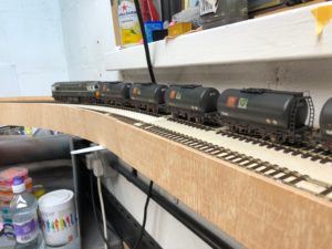
I am fortunate enough to have a dedicated workshop space at home, and whilst it isn’t large enough to build any sort of sensible continuous run layout, there is just space for a continuous run test track around the walls, making use of the rack shelving on two sides to provide some support. It’s a joint effort with my son, who has a small end-to-end layout but sometimes wants to run his OO trains for longer, plus I wanted an OO track to test run new locos before changing the wheels to EM, and of course an EM track for the majority of my models. We thought about trying to make a dual gauge single track, but realised the wider track bed needed for two tracks would not only fit well, but also make the boards more rigid,
Elsewhere on this blog you’ll find the description of the laser cut trapezium boards built for Minories; this is designed to be a low cost project using various bits and pieces from the ‘store cupboard’ as much as possible. It doesn’t have to be that rugged either, but I did want to make it fairly easy to move if needed in the future, and I certainly wanted to be able to take down the section that would block full access to the door – even though it is about 4’6″ off the floor so it is above the workbench, gives a good eyeline view of the running and allows an easy duck under rather than getting onto hands and knees.
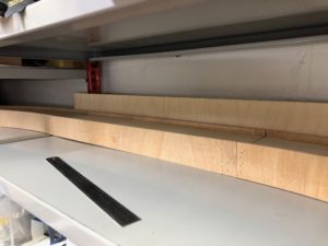
We did some preliminary sketches of the workshop, and worked out that 1m outside radius would fit with some short straight sections between each corner board. To minimise space used, the corner boards are curves with a 12cm wide track bed all the way around.
Timber
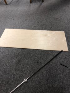
The most expensive part of this build is the timber. As usual I avoided the chain stores, and went to my local timber merchants AJ Ferguson on Uxbridge Road. They supplied a 2440 x 1220mm sheet of 4mm birch ply, cut down into slightly more manageable pieces to transport by car to mark out later for the curves, plus some 120mm wide strips for the straight sections, and as you’ll see to help mark out the angles.
They also supplied some 5mm flexible plywood. I’ve never used the material before, but as we’ll see the aim was for something that would bend easily for the sides of the curves. the 2440 x 1220mm sheet was partially cut up – into 50mm high x 2440mm long strips for the edges (the sheet is of the type to bend on the long dimension – you can get a different version to bend the other way too). I’ve still got over half the sheet left, no doubt for a backscene at some stage..
The final timber used is some 18mm birch ply for the end pieces and cross braces – left over from a previous project.
Marking out and Cutting
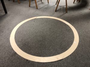
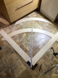
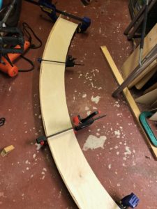
A trip to Keen House enabled us to use the large radius scriber to mark out the arcs of the curved boards. As an alternative, a piece of softwood with a nail at one end as the fulcrum and a pencil at the other would work just as well. At this stage, I wasn’t worried about the 90 degree precision – more about getting the arcs marked out and cut fairly accurately. When giving cutting instructions to the timber merchants I worked out how to just fit the two arcs into a rectangle – any bigger and I didn’t think they would be manageable for the cutting out. Once marked out, we used the Club’s bandsaw to cut the curves. Even with two people it wasn’t an easy job, and in hindsight perhaps a jigsaw would have been easier and made a slightly smoother cut. But here are the basic curves cut to form the circle with at least enough overlap to make trimming to exact quarter circles easy.
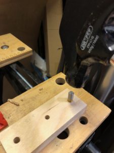
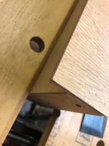
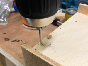
We then cut the 18mm ply into 40mm high strips, which were then cut into 120mm wide pieces to form the ends and cross pieces. Holes were drilled in the ends in pairs for the 8mm dowels (Station Road Baseboards) and M8 bolt holding the boards together. The dowels were tapped into place using a spare ‘other half’ and the hammer – in 18mm ply it’s better to use the 7.5mm diameter drill recommended to go all the way through, then just open out the top very slightly with an 8mm bit to ease the dowel in. In softwood, definitely use the smaller diameter as there is more give. Further 18mm sections to go in the middle of the boards (to avoid twist) and had an 8mm hole drilled to allow for wiring.
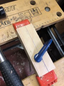
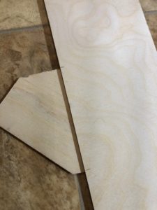
Once back home, we needed to mark out the oversized curved boards to exactly 90 degree angles. Our largest carpenter’s square is about 25 cm long, so we had to improvise using the square and some accurately cut (and checked) sections of ply to make a large enough angle to ensure square cut ends. The ruler enabled us to double check we had the correct centre point. The jigsaw made quick work of trimming the ends.
Board Assembly
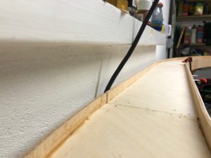
The board structure follows well proven box design, with the wood glued, clamped where necessary and pinned together. In this case we glued and pinned the 18mm plywood ends and cross pieces to the track bed first, and then glued and pinned the flexible plywood to the sides. The downside of the flexible wood is that it is softer, and the pins from the tac gun went deeper. However the aim is for the glue to do most of the work here.
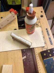
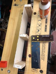
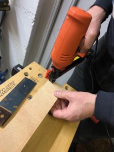
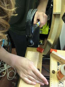
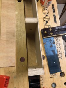
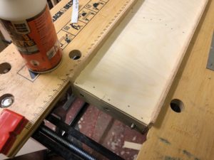
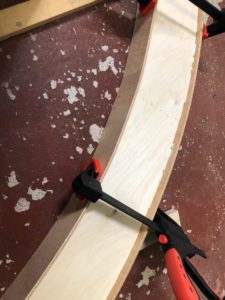
The images show the shorter sections being assembled, as with the curves we didn’t have and spare hands at the critical moments. With the curves, we used clamps to make sure the sides formed contact with the track bed. Before the glue dried, we checked the ends were at 90 degrees and the track bed was level along each board.
Preparation for track laying
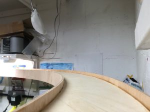
After allowing the glue to dry, we checked that all the boards did actually fit together to form a loop (which they did with one minor fettle of a joint) and installed some small wall brackets on the sides of the room without the shelves to support those boards, checking for level. Then we took it back down again ready for track laying.
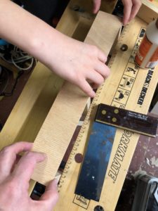
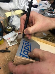
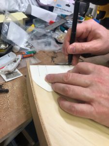
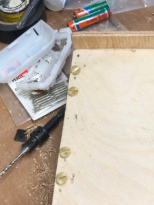
The next stage is to prepare the board ends for the track. The blog here describes the method used in more detail. I marked out the position of the screws using a simple card template for speed – as it’s a test track no need to be super precise, if this was for a scenic section I would have take more care in the exact positioning of the screw heads, and sliced the sides parallel to the rail off to make them less visible.
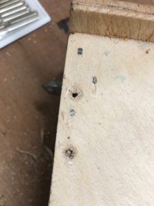
In this case, some of the screws hit the dowels in the board ends. We didn’t have any shorter screws at hand so simply cut the tips of the screws off with a hacksaw before screwing them in.
The EM gauge track is the EM Gauge Society’s product new from the box, that is pretty easy to work with. For the OO, we used a job lot of pre-owned SMP track from the MRC preowned shop. Second hand track is always a bit risky, and something that is worth checking in real life rather than buying online – I normally avoid track that has been previously glued, painted or ballasted. In this case it I did get the chance to inspect before buying, and whilst it had been lifted from another layout and there was some damage to sleepers, the bad ones were simply cut out and the adjacent sleepers shuffled up.
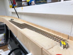
We laid the track a couple of boards at a time, so we could lay it across the joints. Sleepers around the joints were moved away, and the clearance of the rail over the screw heads checked each time. Then using code 75 fishplates to align the rails and allow for some expansion, the back of the sleepers was slightly covered in PVA and laid. We gauged it off the side of the boards using the plastic centre inside from a roll of tape, that happened to be the perfect size, and checked with a small mirror at track level to ensure curves were smooth.
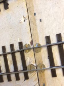

The track was weighted down with handy cans for 20-30 minutes and rechecked for alignment. Then the track was soldered to the screws, checked again for alignment with the mirror before cutting the rails with a slitting disk in a mini drill. We could have used a raser saw, but this was a speed build.
We planned ahead to avoid having sections of track joining near board joints, and to minimise waste of rail. The only slightly tricky bit was getting the last sections into place to close the loops, slotting in both sets of fishplates so the curve fell naturally to the radii of the rest of the circuits.
Wiring Up
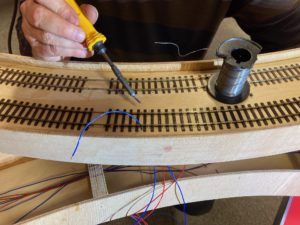
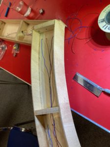
The penultimate stage is wiring the boards up. If it were simply a test track, then we could have put simple 4-way connectors between each board. However we have a plan to test some automation in the future, so to prepare we’ve made each board its own electric section plus a couple of spares to each board, which means a few more wires. First stage is droppers from the rails – I always put a wire to each rail, not relying on fishplates for conductivity. And stick to “Red for Right, bLue for Left” going clockwise round the boards.
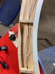
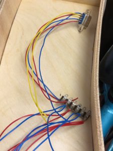
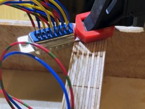
These wires are then commoned on tag strips under each board. Making use of some 9 and 15 pin D connectors in the electric box, and another purchase from the MRC shop of some 25 way D connectors, we then cut, stripped and soldered the wires from tag strip to connectors, and between connectors. Where we used flux to help make the solder joints, we washed it off to avoid future corrosion.
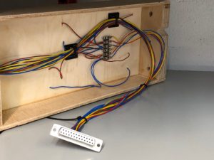
The boards are connected together in two halves – working around the boards from ‘6 o’clock’ to ’12 o’clock’ in both directions from the controllers to reduce the length of cable runs. Then some cable tidying with self adhesive pads and cable ties, plus covers over the plugs to reduce the risk of pulling a wire out when unplugging them. As a temporary link to the controller, we took a couple of 25 way connectors and commonned together all of the feeds from each circuit to a controller.
Before the first train
With the end in sight, we cleaned the track, and felt round the rails with our fingers for any bumps around the solder joints. Once satisfied we re-assembled the boards, connected the electrical plugs through to the controller and got out a couple of reliable locos out.
With a slight moment of trepidation we turned the power on to the EM gauge loop, and watched the loco progress from board to board, and breathed a small sigh of relief when it ran round without stopping. And when the OO gauge loco did the same thing we had a high-five. The project took around four days to cut, assemble, lay track and wire up taking advantage of the Christmas holidays, and we’ve ended up with a more thorough test circuit that we can use whenever we want.
You may also like...
Thursday Track Nights
We are open on Thursday evenings from 7pm to 9pm at our Keen House clubrooms. Visitors are welcome, please come along and introduce yourself.
Address:
Keen House, 4 Calshot Street, London, N1 9DA
Become a member