Building Trapezium Baseboards for Minories
Tom Cunnington
23rd May 2020
9 minutes

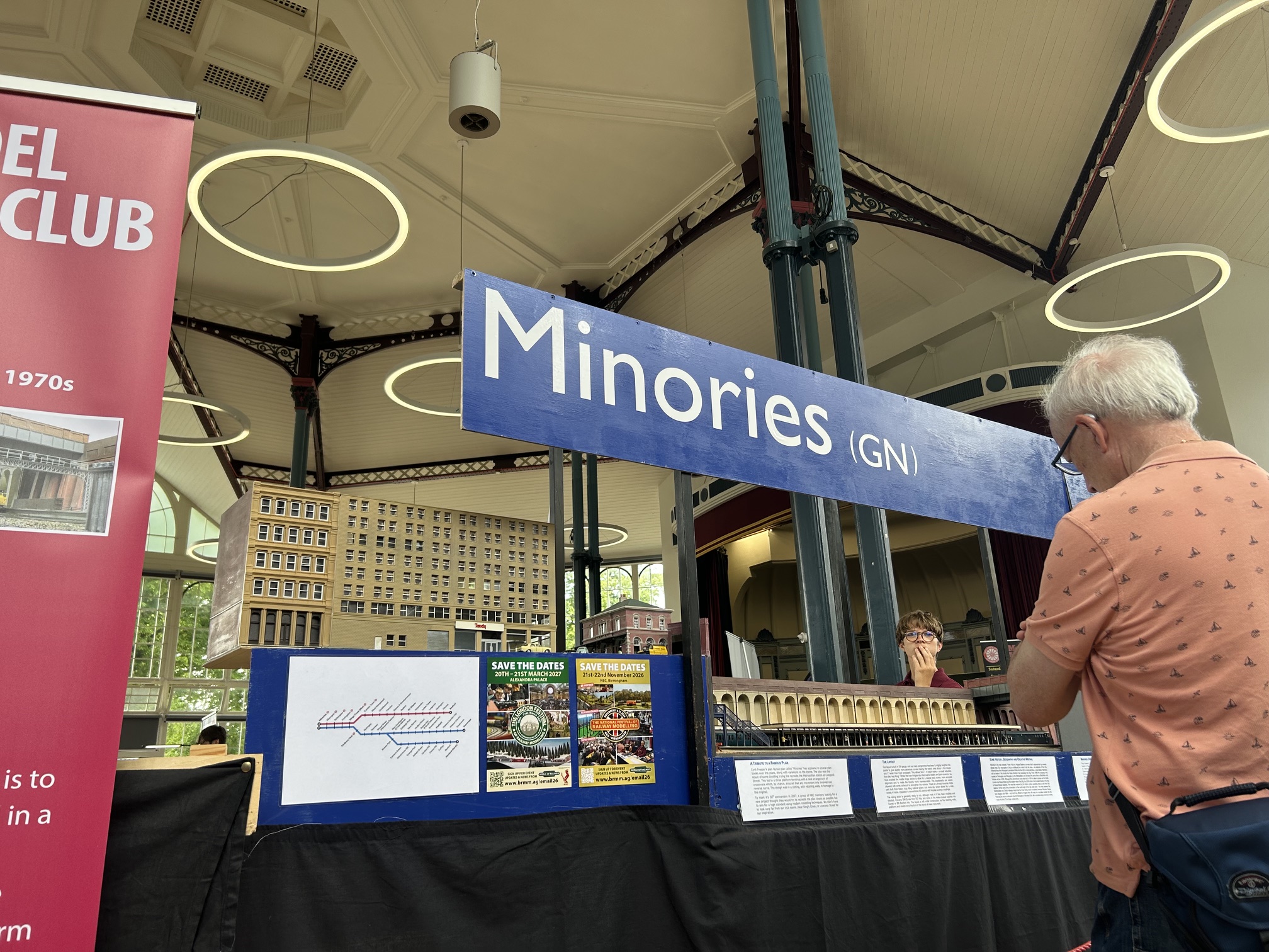
The classic Minories layout is a terminus to fiddle yard design – and that is what we built back in 2007 and how the layout has operated for many years. With a good team of operators we’ve presented a slick service of peak hour trains running in and out of the station’s three platforms at more exhibitions than I can remember. However in our world, whilst the layout is the terminus for the passenger services from the GN and Midland lines in an extension of the Widened Lines beyond Moorgate. The tracks run through the station further eastwards to join into the LTS lines somewhere beyond Fenchurch Street, with links to the diminishing docks and industry along the Thames estuary.
Going Circular
For all sorts of reasons for a while now I’ve been planning to extend Minories into a circular layout – including the restrictions of the 6 road traverser which is beginning to show it’s age, the wish to be able to run trains in circles, and probably most importantly as a precursor to the next project – which if it is ever built will be a larger 4-track circular layout with a through station. With that in mind, my first aim was to consider the boards with the curves.
The aim of the layout has always been to minimise the space it takes to store and transport, and I realised it would be easy to get that wrong here. As an aside the original layout was designed to fit into my car at the time it was conceived – a Polo – to avoid the costs of hiring a vehicle for exhibitions to keep the costs of exhibiting down. It was also designed so that the boards could all be lifted by one person, as there are plenty of times that is necessary. Living in London storage space is also a constraint so the design process has always considered the size of the layout erected, stored and for transport along with the weight.
These principals therefore extended to this project, with the aim is to have enough board and space to fit the track in, but not to have acres of wasted space. One solution is to use curved boards which can by their nature follow the shape of the tracks. They aren’t impossible to make, but getting the cuts right, and bending the verticals to shape takes some time and patience, and then they are also less stable to work on and store on the curved sides. So I looked at trapezium shapes, which have nice straight edges which are easier to cut and assemble. There’s a balance between the size – a six piece circle has fewer joints but more wasted space; a 10 piece has very little wasted space but probably weighs more in total, given the design chosen.
Inspiration
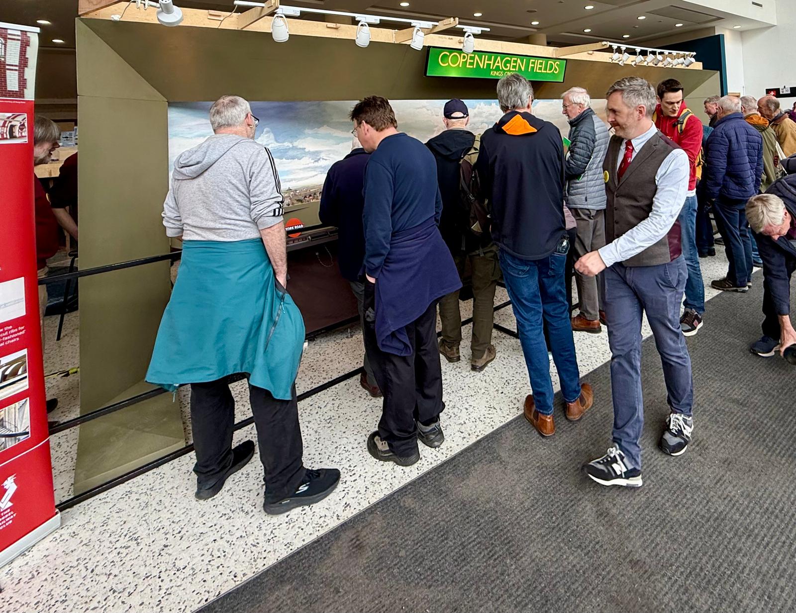
I was inspired by a combination of the box structure used on Copenhagen Fields, and the simplicity of using limited amounts of heavy but incredible stable and strong 18mm birch ply as crosspieces and thinner ply for the rest of the structures on Minories – seen here in this end on section
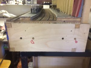
The aim is to use two types off wood – so the ends are the 18mm birch play to give the core rigidity and to provide the strength for the screws that hold the rail ends in place (see this blog). then it is 4mm ply for the rest – double layers for the sides, and a solid sheet top and bottom to make a solid box. Somewhere in the back of my mind I thought I might want to use the boards for another gauge, so the bottom is solid but it could have been a frame that would have made wiring a little easier.. more of that another time. There is ply and there is ply. The material from most DIY shops isn’t in my experience stable enough without significant framing, so I have learnt that it’s worth spending more to get the higher quality versions from specialist timber merchants.
Putting Ideas on Paper
I started by drawing a rough sketch of the design, and working out the angles. Here’s the original sketch, and the more refined version (I wouldn’t call it a proper drawing).
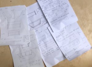
And then made a card 3D 1:10 model just to get a proper sense of proportion.
I realised that there was a fair amount of careful cutting with angles on several of the cuts that had to be accurate. Another member had recently told the story of building the boards for a circular layout to a plan, only to find a series of small errors led to a fair sized gap when they were assembled, and another filler board had to be inserted. So problem solved, but I wanted to avoid that for this project. Chatting about it at Keen House, a member suggested laser cutting the elements to get both accurate and consistent boards. Sounds good, but it needs a CAD drawing – something I have no experience of. Luckily another member stepped in and offered his help, and created this from my sketches:
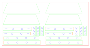
It has each of the components drawn out, with the green colours showing 90 degree outside edges and red lines 22.5 degree angles for the cutting – the blue are cut outs. You’ll see the cut outs for the 37-way D sockets too – that’s the layout standard for electrics as the connector price difference is minimal and it means the leads can be interchanged. The 18mm wood sheet also had holes for the dowels – sized 0.5mm smaller than the dowels’ nominal size as its easier to slightly open out than find them lose – and each end was a symmetrical mirror image.
Test Cut
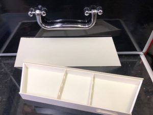
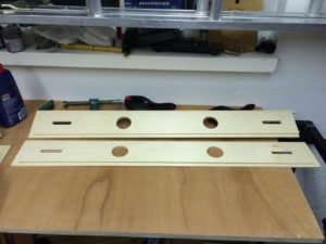
I was worried about the strength of the side pieces, so the first version had only small holes in the side. The sheet has two boards worth of pieces, and I thought it was best to try one sheet of 4mm ply first (plus the sleet of 18mm that had enough parts on it to do the whole lot and more) to check it worked. The cutting was undertaken by a company in Uxbridge, who were very efficient and after a few days I picked up the order – and did the first assembly. (The picture below is them modified later for another project – but shows the original pieces)
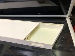
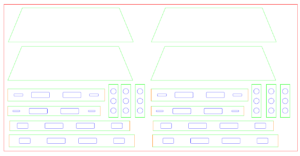
But with those small holes and a solid base it would clearly be very difficult to wire up, so we adapted the design to this – which whilst still tight to wire was much better – and provides a good handhold whilst retaining enough strength.
I went for broke and ordered enough for all 8 boards, and this time the cutter missed the angled cut on the side ends which are essential to get everything to line up. I was tempted to try and fix this myself, but the whole point of paying for the cutting was to get these angles done accurately, so after making a contribution to the cost of the wood, I had another set made which came back just as needed. Meanwhile, that spare pile of wood has gradually been used to make other boards for the layout, my son’s current layout with some other bits still on the shelf.
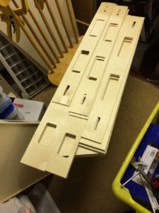
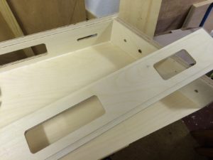
The cutouts make aligning the two layers that make the sides simple – although they do move easily with the glue in place so some care is needed to hold them as they dry. You can see here part of the pile of pieces – showing on top the inner layer of the ‘inside’ edge of the boards, and further down the slightly wider ‘outer’ edges and the longer outside edges.
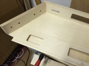
Construction
I’ve lost some of the pictures of the actual build, so here is a hybrid showing the actual boards as they piece together. You can hopefully see here the way the sides overlap with each other, creating a ledge for the tops and bottoms to rest on. Plus also a small lip on the top and bottom to protect the track. Later I added small wooden blocks so that the boards stack and interlock which makes them incredibly stable in the van, and on the shelf in my store room. The only element not shown here is the three cross pieces that provide more support that are shown above in the drawings.
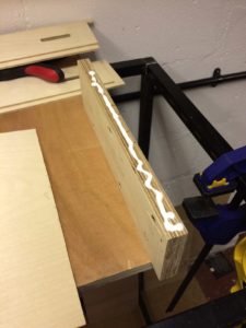
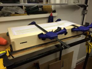
Here are pictures showing the technique from a later board. There are no screws in the construction – it’s all wood glue and nails from a small nail gun with the glue doing the hard work. Firstly it’s worth checking everything does line up as a dry fit. Then glue, place wood together and clamp, checking it is all aligned. It’s amazing how easily the joint moves as the pressure of the clamping squeezes the glue out. Then the nail gun is used to hold it in place as it dries. The joint is checked again just in case anything isn’t right – as it is easier to pull it apart now rather than later. If any glue seeps out, then I just wipe it off with a finger and in doing so create a clean edge.
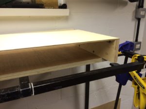
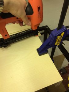
I then generally press on and do the whole board quickly. It means if there is any small adjustment it can be pushed in or out as the glue is still wet. So the whole box is built, glued and nailed and checked for squareness before setting.
Track Position
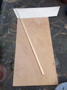
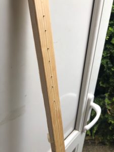
One thing I hadn’t thought about – and might have had etched into the 4mm top sheets – was the track position to get concentric circles as the spacing is tight. So after building the first board I paused and created a compass to mark out the rail positions. It’s a simple piece of softwood, with the hole drilled out and small nails put in and masking tape to hold them in place to score into the wood. You can see how it was done here.
The remaining boards went together in a production line over a couple of evenings – the only other detail to mention is the use of dowels and surface mounted clamps to hold the together from Station Road Baseboards.
Assembling the Boards
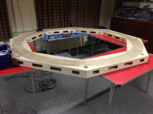
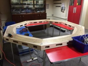
The resulting boards made a perfect shape without gaps when assembled together, and are very light. The whole set of eight was within carrying weight, but realistically four stacked together is more manageable – and with the track and wiring in place is just the right load for one person.
Then came track laying – which uses the Copenhagen Fields method of brass section, bent in their bespoke (and award winning) mangle to the basic curves, but then held down with tiny brass screws drilled out and counter sunk with a centre drill bit (we’ll try and write a blog on this soon…). Below is the circle complete, and under test as a simple 4 track test track at Keen House.
Conclusion
I’m really pleased with the design and construction, but there are a couple of things I’d have differently. I would probably have spaced the tracks out by an extra cm, and made the boards 2cm deeper as whilst my hand just fits in, it’s tight for wiring. In the end I removed some of the brass rail to create a better alignment with the fiddle yard and start to spread the tracks to maximise siding length.
So that covers the boards to get the track round the corners, coming soon the story of the similar but slightly different new main fiddle yard boards.
If you’ve found this useful, why not check out other blogs – including building track, converting models to EM Gauge or about our layouts including Minories
And find out about the benefits of joining us
You may also like...

Thursday Track Nights
We are open on Thursday evenings from 7pm to 9pm at our Keen House clubrooms. Visitors are welcome, please come along and introduce yourself.
Address:
Keen House, 4 Calshot Street, London, N1 9DA
Become a member