Sarum Road – Story of a OO gauge layout – Part 1
Michael Joseph
14th May 2020
7 minutes

“Sarum Road” is a model of part of a locomotive depot set in the year 1956 in South London. The yard is small but busy, with a selection of Southern and BR types, as well as occasional LMS and NE locos that have crossed the Thames on transfer services. On the viaduct is a shuttle passenger service to a small, temporary station – the area as a whole has still not been rebuilt from bomb damage sustained during the war. There is also traffic on the running lines behind the viaduct.
The layout is operated from the front, but can be viewed from both sides with movable backscenes so that the loco shed becomes an industrial works with typical small locos in the yard. It has been built so that even the wiring can be viewed on the underside of the boards.
Sarum Road is designed to be light at under 30 lbs, (13.5 Kg), for portability on public transport, only 9’ (2.74m) long to fit in a small house and to be fairly easy, ie quick, to build. The lightweight baseboards have been built from 3mm ply and a PC used to generate drawings, architectural details (eg the viaducts), wiring schedules and the control panel. The scenery has been created with a number of unusual techniques such as foamboard for the viaduct, printing my own brickpaper and a novel method for the general yard area.
The project has not needed any specialised tools (with the exception of the traverser) and has been built almost entirely in the dining room on an old(!) dining room table.
Mike Joseph details how he built his lightweight micro layout over the next 10 weeks – updates published every Thursday evening. It’s the sort of layout that could fit in almost any home, and provides good operating interest, whilst be light to carry and easy to store.
REACH FOR THE PLY! – The Prologue
Here I am, happily ensconced in front of a monitor, typing away into a not terribly quietly steaming PC and the thought crosses, nay, rages across the brain cell that it is about time that I did a bit of modelling.
The trips to the Paris fashion shows have been booked already. This is MJ among the shapely ladies on the cat walks, the tales of the designers, the press launches and the sheer glitz and glamour, but, in fact, that is another story.
I am actually envisaging the contemplation of the maybe-sometime construction of something not entirely dissimilar to a model railway. I appreciate that many of you are shocked to the very quick of being by this news and that such information has not been disseminated nor even mentioned within the walls of the Club for many, many years. I can feel the waves of horror that the thought of multiple and very similar, unpainted plywood structures that I have in my possession will cause when they apparently breed in profusion. The sight of a model railway consisting of several hundreds of such buildings, would, I am sure, bring much angst and drive many of our members to a premature pint at the bar.
The planning of this most signal project is perhaps firmly on the tracks and its station in the life of this particular fat controller is almost probably assured.
And so as the train of thought rolls inexorably towards the probably endless tunnel of destiny and as the shunter in the skies of time watches aghast as the fly-shunted wagon of fate smashes through the buffer block of metaphors, MJ will continue this story in the next Bulletin.
And now the saga starts…
REACH FOR THE PLY! – Introduction
This is intended to be the first of a series of articles tracing the building of a layout, using simple tools as far as possible (kitchen table style) and a PC to print some of the difficult bits. Useful items such as a small spreadsheet for calculating weights, photos, diagrams and other notes will be put on to the MRC’s website, (www.themodelrailwayclub.org) as the project progresses.
The project really started in October 1999 shortly after I bought a scanner. The box was kicking around the kitchen for a while and then slowly the penny dropped that I could fit a layout into it, or at least into a purpose built unit of about the same size. Coincidentally, this box was an almost exact fit into the cubby hole above the stairs and suddenly, by having suitable storage in an otherwise small house, the project became feasible. The brain cells started plotting…
After playing around with various configurations of boards, track plan and construction methods, the project gradually resolved itself to the point where building a layout (!) could start.
Constraints
The physical constraints of this project are:
1. The layout must be easily portable and light, eg ideally under 30 lbs (13.6 Kg), so that it could be treated like hand luggage.
2. It has to fit into an awkwardly shaped cubby hole.
3. Max length about 9 ft (2.7 m) to fit into the dining room.
4. Simple construction, simple electrics.
5. Overall construction time to be under one year (work permitting) ie quick.
6. Structurally strong.
7. Use simple tools for construction – kitchen table style.
8. Basic woodworking skills.
The modelling constraints are:
1. Period set about 1956 on the old Southern Region so that both the early and later BR logo could appear. Servicing area for cross-London services as an excuse to run foreigners.
2. Good ready-to-run locos, etc for the period are also easily available.
3. Environs are a loco depot, with one or two running lines and a railway viaduct forming a scenic break at the back..
4. Reasonable scenic breaks and backscene.
5. It must look right – architectural details, etc to be accurate as far as time allows.
6. If possible, to be built as a double-sided layout, ie can be viewed from either side, as an MPD from the one side and (if feasible) as an industrial site from the other glimpsed through the arches of a viaduct.
Planning
The fun bit – sitting at the MRC and chucking ideas at Pete Colton, listening to the others and generating ideas, silly, impractical and useful!
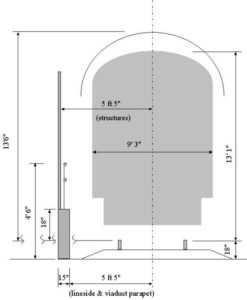
The depth of the intersection bridge in the middle of the viaduct was calculated at 1.5″ for an 18″ span (3.9 and 45.7 cm respectively) ie 1/12 of its overall length. (Note: the usual figure for calculating the depth of an older girder bridge is about 1/10 to 1/12 of the overall span). There should be cross girders on the underside of the bridge supporting another pair of girders running longitudinally and it is on these girders that the bridge plate and running lines lay.
The Layout
Diagram 2. Track Plan (9ft overall)

a. The Southern Layout
The up (London) side of the layout is to the left, so that the through loco shed and workshops are ‘off stage’ in the Upper Yard. There is another, big, viaduct that cuts across the yard and provides the scenic break (no trains will be run on this line).. The Lower Yard is to the right and the main viaduct at the rear of the layout runs approximately north-west to south-east. The feel is intended to be somewhat like Stewart’s Lane in a cramped site, almost surrounded by railway bridges, etc.
The period is only ten years after WW2 so that there is still a lot of bomb damage evident. There are scars in brickwork with large patches of new brick in the viaducts. The rear viaduct itself is part of a flying junction to a branch and is electrified with a shuttle service using an ex SR 2 car unit.. The lower line is a steam service with the very occasional shiny bright and new DMU or even a Hampshire unit. It will be properly signalled to work the junction to the yard with signalling inside the yard to cover access to the main line. All working lines are bi-directional.
The down end serves a nearby station with good tram and bus connections so that most of the shed staff come through that station and use a push-pull service to a staff only platform in the yard area. Cramping the yard is a bridge abutment for another line that originally passed over the yard to form a junction with the high level line but the steelwork for this bridge has been removed, leaving only the brickwork. Further down the yard (off-scene) are the facilities for water, ash and coaling in the Lower Yard. The Upper Yard is hidden behind the viaduct and will probably have a four road traverser. The locos are substantially SR constituent companies, BR types and a sometimes an ex-LMS type that has arrived via the West London Extension or Holborn viaduct.
b. The Industrial Site
This facet of the layout is still very much being planned, with either a location around the back of Waterloo or perhaps to base it upon the small industrial area near Redhill. The backscenes are to be double-sided so that the face now showing has factory/industrial buildings. The brickwork colour, etc has to be right for the area.
Option 1: Waterloo
Around the back of the station, there used to be an enormous network of industrial lines between the station and the river. So the layout could comprise of an industrial site, wharfage traffic, coal and parcels. Small four and possibly six coupled locos such as a B4, Manning Wardles, and ex-WD types. There could still be an electric service over the viaduct. Gated access to the yard area off the main-line would ‘restrict’ access, with the gates left in the open position. An occasional pick-up goods service would collect and return wagons.
Option 2: Redhill
Brickworks or a papermill: – with the last option fireless locos would prevail with perhaps a diesel shunter and a sentinel type. Otherwise the environment would be very similar to the first option.
You can read other instalments here: Part 2, Part 3
This article was originally published in The Bulletin, with almost 20 years of past editions available in the members’ area of our website. Find out how to join us today
You may also like...
Thursday Track Nights
We are open on Thursday evenings from 7pm to 9pm at our Keen House clubrooms. Visitors are welcome, please come along and introduce yourself.
Address:
Keen House, 4 Calshot Street, London, N1 9DA
Become a member