Track Building – Part 2
Tom Cunnington
31st May 2020
7 minutes
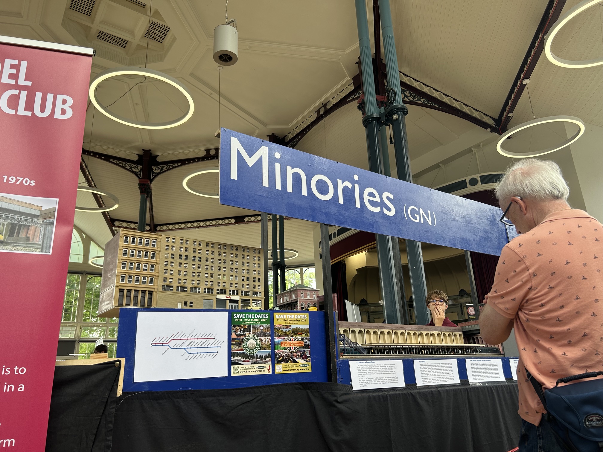
In Part 1, I outlined the plan to build new track and points in EM gauge for Minories for the expanded fiddle yard. Here’s how it went, starting off with how it ended up – the full sized layout up in the library at Keen House. Most of this track building work took place in 2016 and 2017, but it’s taken the lockdown to get round to writing it up…
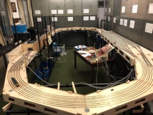
The new continuous run fiddle yard is a series of elements that are designed to work for the current Minories, but the bulk of it is also to be reused for my next project which is a four track continuous run layout. In the Minories set up the arrangement is as follows: working counter clockwise from the station platforms (on the left of the picture above) the two tracks coming out of the station throat split out to four tracks to go around the 180 degree circle nearest the camera – so there is a junction that splits the roads out into passenger (outer pair) and freight (inner pair) lines. The class 31 is departing the station on the passenger lines. The back straight storage sidings themselves are then two separate areas – 6 loops on the inside ‘goods’ lines consisting of two in each direction on the outside of the formation and two roads in the middle that are normally a third loop in each direction but also allow for trains to reverse directions if needed using a trailing crossing at either end. The goods lines then come back together and use just two of the four tracks back round the 180 degrees and connect back to the scenic section under the station building.
The passenger fiddle yard lines (on the right hand edge of the photo) have four terminating lines for Minories – so they need to be able to be switched to both the arriving and departing lines. To maximise siding length, these have a scissor crossing and slips which is the shortest formation of pointwork to connect the arrival and departure tracks to the four sidings. These will for the next layout be another pair of loops in each direction, and have a simple set of points to bring the two tracks back to one at the far end. On that layout, the two loops will normally be considered and operated as independent with no or very limited exchange of trains between the two pairs of lines and sidings.
Although the curves look like they are lots of track with no purpose, they form part of the storage, as each pair of trapeziums is an electrical section and holds a standard length passenger train of Loco + 4 coaches, or a long freight train. That means that with an alert fiddle yard operators there should always be a train ready to enter the scenic area, and space for one to leave, when needed by the station operator.
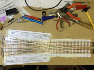
2 splits to 4
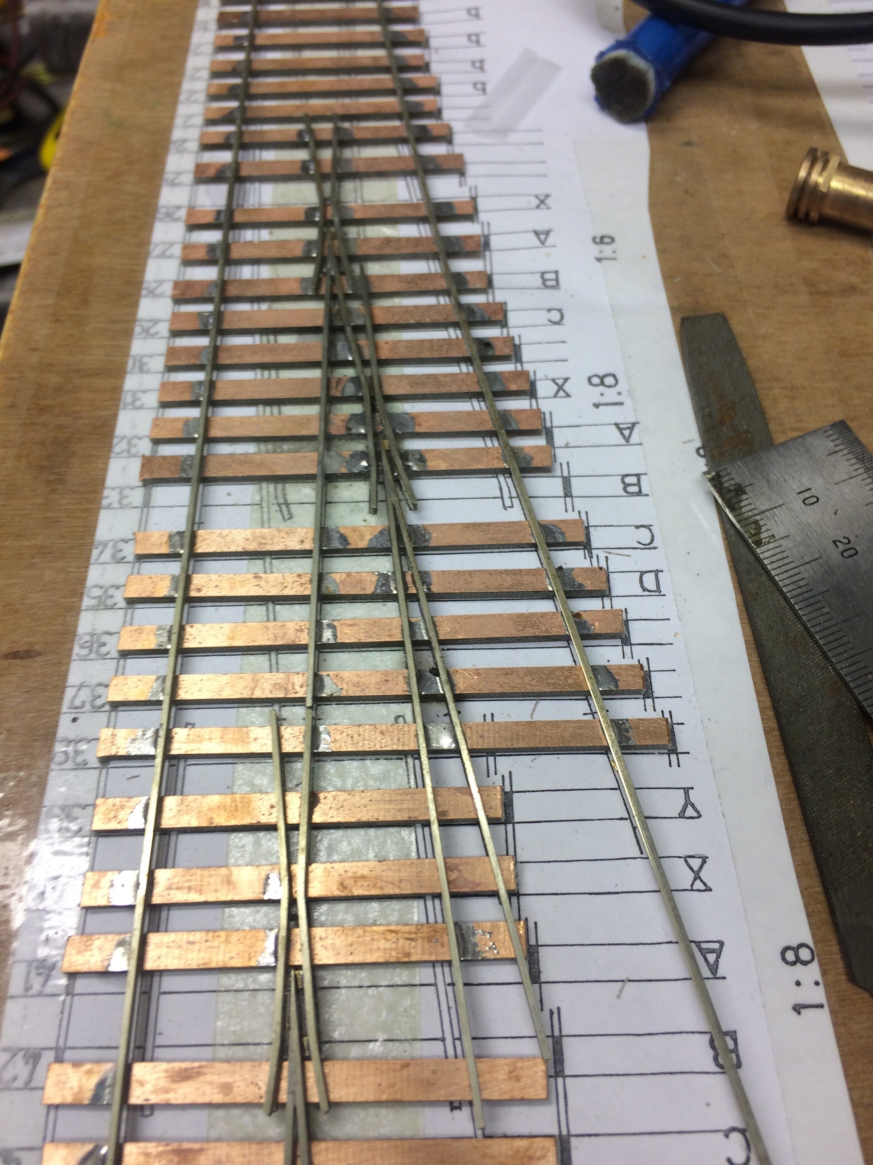
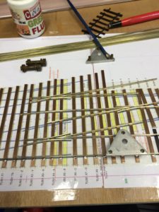
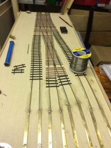
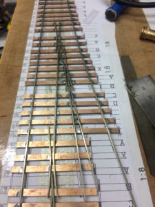
Starting off with the easy one, the ‘splitter’ board is a fairly straight forward two to four track junction, consisting of two turnouts and a crossing. This was planned out in Templot, and the plan fixed down to a good flat piece of ply wood. I normally build directly on the baseboard, but this time the track came before the boards.
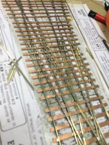
Copperclad sleeper strip was cut to length and held down with double sided tape – but with the side of the tape touching the sleepers made less sticky by applying it to my jeans briefly which leaves it with enough fixing strength to hold everything in place during the build, but makes it easier to remove the formation when built. The photo above shows the sleepers in place.
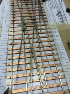
The following shows the tracks and common crossings going into place. Although on a single point I would normally start from one side (normally the straight) and work across, in this case I started from the middle and worked out. There are plenty of gauges in use here to ensure everything does line up – the gauges are of course what is important, the paper plan is only used as a guide. The trusty flux and flux brush plus a glass fibre pen are there to clean up surfaces and ensure a good soldered joint.
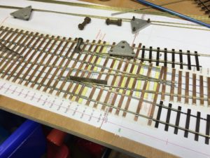
The plastic sleepers are used as a way of holding the gauge of the rails on either side of the points, and also act as a good way to avoid catching the end of the rail at this delicate stage of construction.
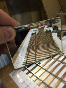
I can’t get my eye down close enough to the rails to check that everything is in line, so the trick here is to use a small mirror to check the alignment and spot any kinks in the rails.
Once the board was built, the track was laid and extended to the board joints. Initially I used the same brass strip as the curves, but revised this after the shots taken here to have plain track from the points onto the first curved board.
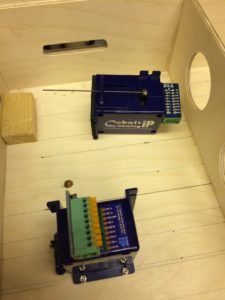
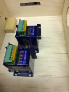
This board uses spare pieces of wood from the Trapezium project, so wasn’t really designed for point machines. My preferred Tortoise units don’t fit in the normal position without protruding from the bottom which would lead to them being damaged in transit, and although I debated mounting Tortoises sideways decided to try out these Cobalt motors which are slightly shorter and do fit. They are neat units, but slightly noisier and I don’t particularly like the push in terminals for the electric connections, preferring a soldered joint. In fact wires have come out a couple of times at shows – possibly shaken loose by the travelling – and a next stage will be to solder them on somehow.
Goods Loops and a Threeway point
In normal operation, the non-passenger trains stay on the same loop all the time – ie clockwise or anticlockwise. Although there is enough space to store 3 trains in each direction on just the loop around, I wanted some loops to hold extra trains and allow rotation. Sometimes it’s good to reverse direction without having to handle the stock, so there is one siding on each loop with a trailing crossing. Just occasionally a passenger train slips onto the goods lines, and needs to be reversed too…
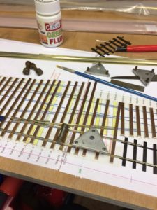
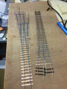
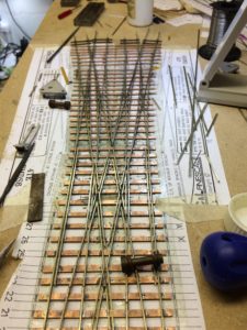
Again I checked the lengths of siding, and realised that one end needed a three way point to give the loops enough length, so used the EM Gauge Society template. Construction is about halfway through in these shots – there is no straight full stock rail (which is a good datum to start from) so like the junction above I focussed on getting the three common crossings correctly aligned, and worked outwards from there.
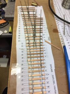
Here’s the threeway point and the trailing point ready to lay, and then in place (left and middle) along with the rest of the anti clockwise loop junction – with the uni-direction loops on the left, and the road that is reversible back clockwise third from the left. The clockwise sidings head off to the right.
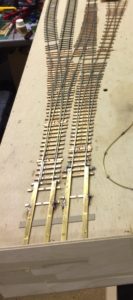
Here’s the other end of the good loops – a more traditional fan of B7 points – viewed from the other end. Thus from the right are the two anti clockwise loops, the two reversible sidings and then the two unidirectional clockwise loops. The four tracks on the right are the passenger sidings.
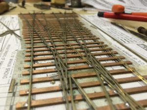
Scissors
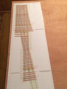
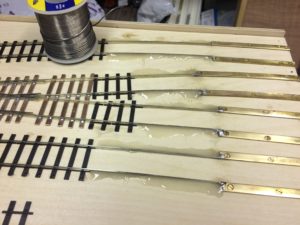
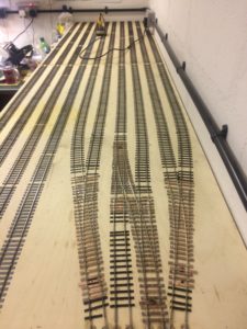
The most complex section is the passenger sidings, where the two running tracks need to split out to four roads. Starting with the almost finished product you can see this is made using B6 double slip C&L templates overlaid onto B6 plans.
These pictures show some of the progress, gradually building out the sections, soldered on the copper clad sleepers and checked regularly all the way through using gauges. The beauty of soldering is the ability to adjust if it isn’t quite right, and I’ll admit there were a few adjustments made in this as we went.
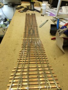
So there we are, a series of points that for various reasons took longer than I thought to build, but which have been laid and made their first outing in November 2017 at Tolworth and then Wakefield.
Look out for my other blogs on baseboards and baseboard joints and the main layout page here
You may also like...
Thursday Track Nights
We are open on Thursday evenings from 7pm to 9pm at our Keen House clubrooms. Visitors are welcome, please come along and introduce yourself.
Address:
Keen House, 4 Calshot Street, London, N1 9DA
Become a member