Minories Fiddle Yard Control Panel
Tom Cunnington
20th June 2020
6 minutes
Every layout needs a control panel – well all of mine do because I haven’t progressed from DC control as I find traditional DC control still works perfectly well and I’m not too bothered about lights and loco sound.
The extension of the fiddle yard on Minories meant a new fiddle yard control panel was required. This isn’t a work of art, and I’m no cabinet maker, but it does the job of controlling trains well so here’s how I made it.
There are only really two key things for this control panel to worry about – setting the points correctly and linking the correct controller outputs go to each section so that trains move when they should, but just as importantly don’t move when they shouldn’t.
The Front Panel
This is what the various switches are mounted in, and from bitter experience it’s vital to make sure there is enough room between each switch to mount and wire it. So the first step was to mark out the line diagram and check the various switches fit.
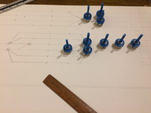
With that done, I sandwiched the piece of ply to form the panel between two pieces of scrap ply and taped the paper drawing on the front. This ensures the holes in the facia itself are clean. I made sure I had marked the right diameter of hole for the rotary and toggle switches and then took it up to Keen House and used the Club’s bench drill for speed and vertical accuracy.
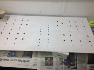
Next painting….
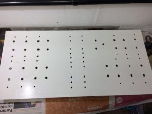
Then the switches installed and tightened into place.
Controlling the Layout
I guess this is as good a time as any to try and explain the method of operation and control. There isn’t a timetable, and not much of a formal sequence although there is a natural rhythm to how the layout operates with DMUs and loco hauled trains going in and out most the time to represent the peak hour service. Every so often there is a flight of freight trains to represent the off peak.
The fiddle yard operator normally controls all of the layout that isn’t the scenic section. But there is obviously an interface with the scenic section, and the aim of the operation at exhibitions is to allow each operator to feed the other trains without the need to constantly communicate – ie the station operator should always have an empty section to drive a train out of the station into, and the station operator should always have a train ready to pull into the scenic section to ensure we can keep a flow of movements to keep the viewer entertained.
Sections
Each pair of trapezium baseboards is an electrical section, and there is another section covering the junction in each loop. Each of these section ‘cabs’ has a rotary switch selecting any of 6 controllers, and an on/off switch to avoid any unwanted power feeds whilst switching between cabs. The 6 cabs are the four outputs from Gaugemaster quad controller (one nominally for each of the four fiddle yard loops) and two feeds from the scenic section. These latter ones aren’t the two controllers used on the station panel directly, but the track feeds from the arrival and departure roads, so the fiddle yard takes the same power source from the adjacent arrival and departure roads to make sure trains transitioning have a smooth handover. Therefore it doesn’t matter which configuration the station controller has set up, the fiddle yard cabs link to the cab output for the relevant section.
Therefore the whole layout can be driven from the station controllers, and with the right roads set up trains can run round in circles controlled from the station.
Handover Sections
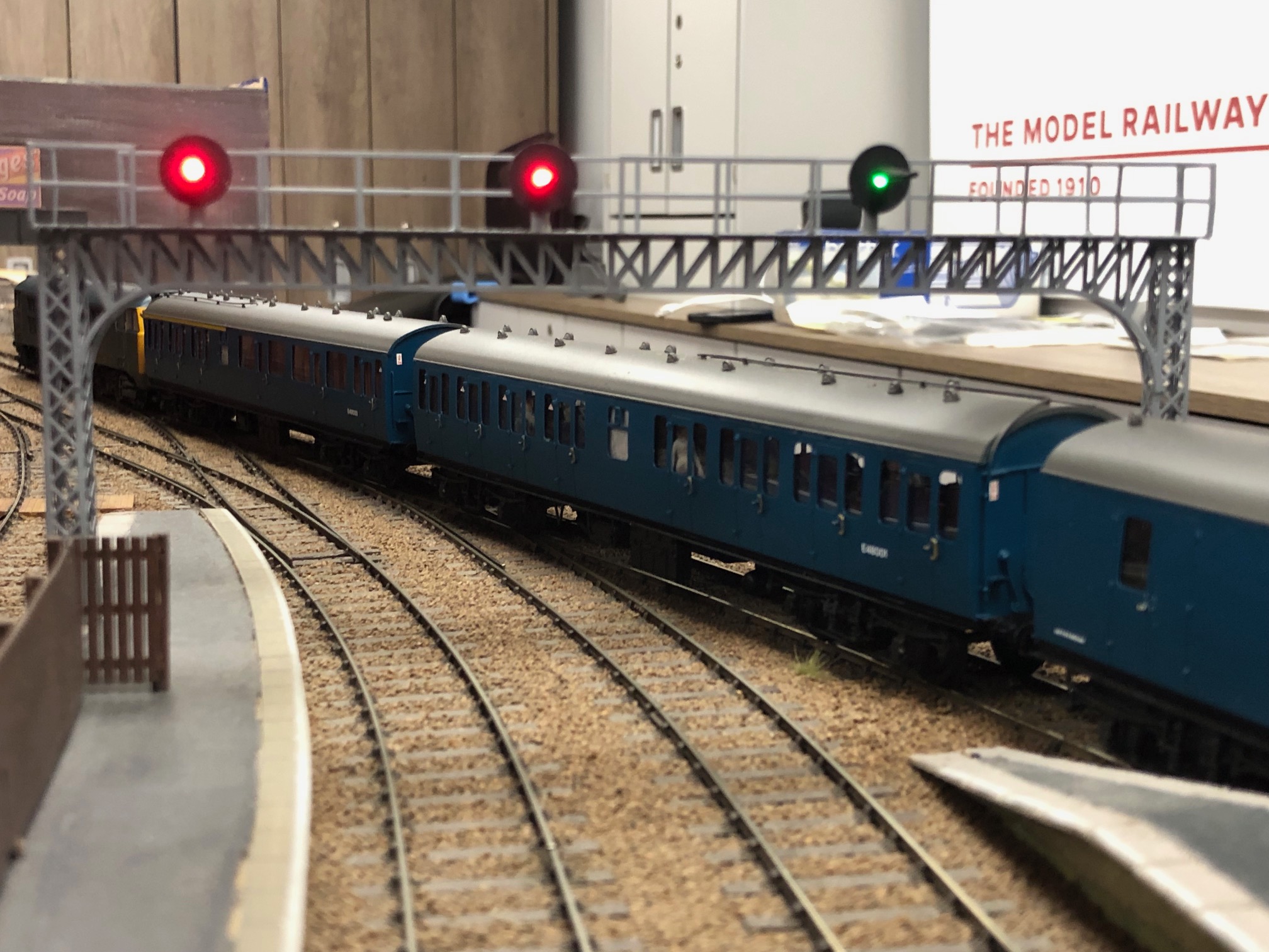
The three fiddle yard sections immediately before the station as trains normally enter (see the sleeper set and Class 105 in the picture at the bottom) have a setting where the fiddle yard controller can drive a train up to the stop point, and then gives control to the station operator. The station operator uses a “push to make” button on their panel to bring the train into the station when they are ready. Similarly the station operator has the ability to drive a train out into the first sections of the fiddle yard on each loop. Therefore the two operators can work together by feeding trains to each other without worrying too much about the order.
The sidings at the back are split into two sections, allowing two short or one long train, and can select power from the arrival or departure end. Up to 10 medium length trains can be held in each direction the goods loops, but in reality it’s normally 4 or 5 trains in each direction which gives enough variety. The passenger sidings can hold up to 8 trains.
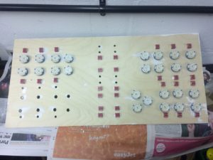
Back to the panel – here are the switches going in, as seen from the back.
The Base
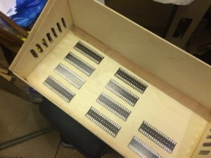
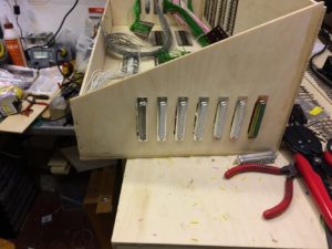
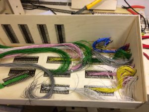
Of course a panel needs something to sit in, and the knitting that distributes the power out to the baseboards. The box is simple ply construction, using pieces left over from the trapezium baseboard project (hence the angles and length – the ends are cut off the sections that form the base and the facia). The most difficult thing was cutting out the holes for the 37 way D connectors. There are currently 12 boards powered – but two boards have two connectors, one for track power, the other for point control. So the fourteen D shaped holes – 7 each end – were cut out with a router before the sides were assembled. Below shows the box, with the connectors in place and the tag strips that are linked to the D connectors laid out.
Then comes the wiring – firstly from the tag strips to the D connectors. It takes a while but I find it therapeutic and suddenly I had finished them all.
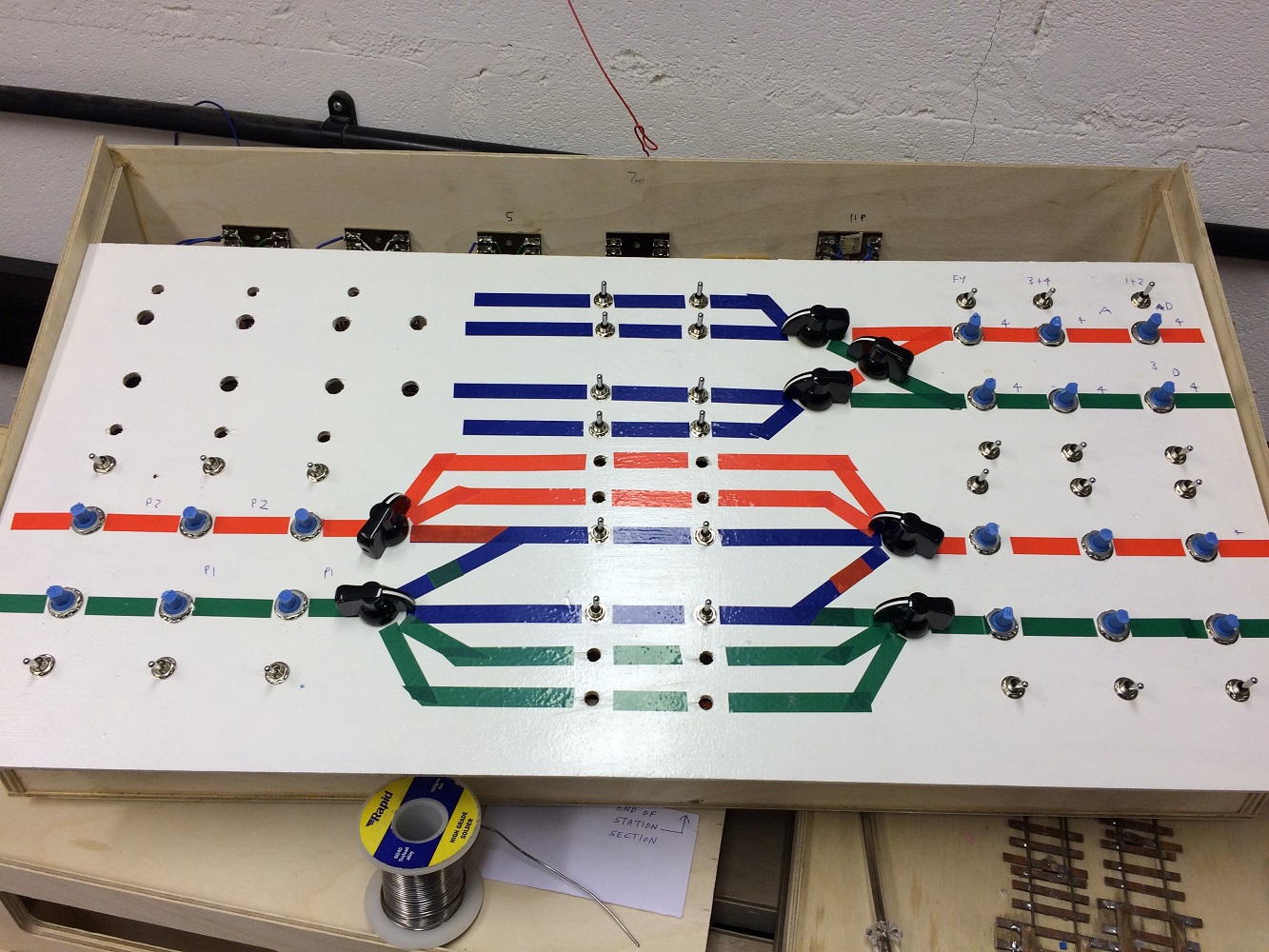
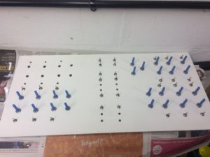
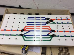
Then came the wiring of the switches to the tag strips, and finally the coloured tape on the front to show the track plan. Green shows anti clockwise only, red clockwise and blue either direction. Here only the point controls have the black pointer knobs in place – the sections have coloured round knobs, and there are a few more section switches to go in.
Nearly Finished
I still need to make and print out the position indicators for the cab control sections switches, but actually the operation means they don’t have to be changed very often so it’s not been a hardship.
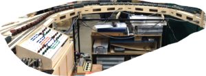
Here’s the panel in use at a recent exhibition, showing the loops in use with 4 trains held on the curves, with the ECS sleepers on one line and behind it on the further loop a Class 105 – both ready to be pulled into the station. The quad controller is on the table in front of the control panel. The shelving unit on the floor under the layout is the storage boxes for the scenic section, which double up as storage at shows.
There’s more on the metal legs, and how they have been upgraded, coming soon. Find out more about the layout here, how the fiddle yard baseboards were built in Bulletin 515 (July/August 2020), building the track here and how the sleeper coaches were renumbered here
You may also like...
Thursday Track Nights
We are open on Thursday evenings from 7pm to 9pm at our Keen House clubrooms. Visitors are welcome, please come along and introduce yourself.
Address:
Keen House, 4 Calshot Street, London, N1 9DA
Become a member