Sarum Road – Part 4 – Track Laying
Michael Joseph
4th June 2020
5 minutes

You can go back to the beginning of this series and see the previous instalments here: Part 1, Part 2, Part 3
Each section of rail, irrespective of fishplates, etc, has its own wire droppers soldered to the underside of the rail to ensure electrical continuity. The rail sides were chemically darkened using gun blue before laying. Each was offered up, drilled through the board and then glue applied, often using the droppers to pull the section down firmly onto the glue. Rail was lined up by the old trick of sighting along the rail and removing any kinks.
The track was laid using Evostik to glue it down (later PVA will be used for the ballast and therefore will not affect the Evostik). The ballast will only be laid once I am happy with the track and wiring. I will be using pva and the finest ballast I can get.
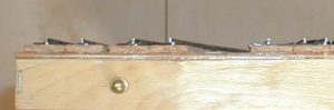
To ensure alignment of the rail over baseboard joints, it was laid as a length across the joint over ½” No. 2 brass screws (from Apsley DIY) screwed into the baseboard ends (remember that these were double thickness?). The screws were put into pre-drilled holes, and screwed down to a fixed height using a crude height gauge made from a small bit of plasticard. The heads were then surgically removed with a Xuron cutter and filed, again to a fixed height using another edge of the plasticard gauge so that they just fitted under the rail and were then tinned. Sleepers were removed from the rail section above the joint and the rail tinned, laid, soldered and when the glue was dry, cut with a saw. Once the sleepers are replaced, the screws are almost invisible.
Pride Goeth Before a Cork-up
I was going to have a loco lift on a short spur but removed when I realised that the track was getting too cramped and decided to put in an ash pit instead for visual interest… but I forgot something in my haste, didn’t I?
One board was to have been free of under-side encumbrances so that it could be used to store the legs for transport. Guess which one I chose to put the ash pit into? And guess whether I had cut the slot before or after realising this? The plan was infallible apart from the fallible fool executing it.
After having neatly cut the slot what was to be done with it? Fallible fool decided to engineer in a slight rise of 1 in 80 to the pits didn’t he? Fallible fool created a lot of extra work didn’t he? Now the pits are on a very slight rise in ground level and perhaps this is the beginning of the slope up to the manual coal stage. Perhaps*.
The rise is built up using 1mm ply from a regrettably defunct model aircraft shop, but model shops do stock it. The overall height is about ¼”, (6mm) and the total depth to rail height is about a scale 3.5 ft (1m), just about deep enough for the real thing – the hole on the underside of the board was closed off with another piece of 1mm ply.
Electrics
There are four points (no pun intended) to be considered here and they are:
1. This is the bit I ain’t too sure about!
2. This is the bit where I am glad I am a member of the Model Railway Club ‘cos they’ve all done it before!
3. And I would rather learn from someone else’s mistakes than my own – it’s cheaper and less painful that way!
4. If in doubt – ask! So I did…
I do not like wiring direct to the connectors because if there are problems, it becomes a nightmare to sort out. Tag strips were used although this would double the number of soldered joints but they are a lot easier to change.
First I got organised. Three jumper cables were created, using 25-way male D-type connectors to create a short 25-core cable. All available terminals have been used to allow plenty of spare capacity. Then a female connector was soldered to a series of wires connected to a tag strip using a crude jig to hold the two lumps in place while soldering. These were fixed with 3mm nuts and bolts to the underside of the baseboards and laid out as neatly as the rails and points above would allow. The nuts and bolts came from Apsley DIY, the electrical bits came from Tandy and especially from All Components of Hereford. The connectors and tag strips are now fixed for the life of the layout.
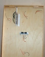
Pin 25 is the common return and on the tag board, tags 25 to 28 (ie any spares) have been ganged together for the common return from the various units on the baseboard. A notebook is being kept of the wiring connections as they are being made.
There is a feed from the control panel to each of the two middle boards and jumpers across each of the three baseboard joints.
Tag strip is used for the connections to the pointwork and to the motors and then the runs of wiring are run in straight lines to the connectors.
In theory all I now had to do is join up the dots…
And whilst on the subject of electrics… The control panel mentioned in the previous article was redrawn slightly, again using MS PowerPoint, printed and this time laminated onto 1mm ply, encapsulated and then punched with a single hole punch – the holes made are almost exactly the same diameter as the miniature switches used. I created a new panel in about 30 minutes, a lot easier than bashing aluminium.
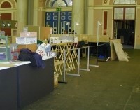
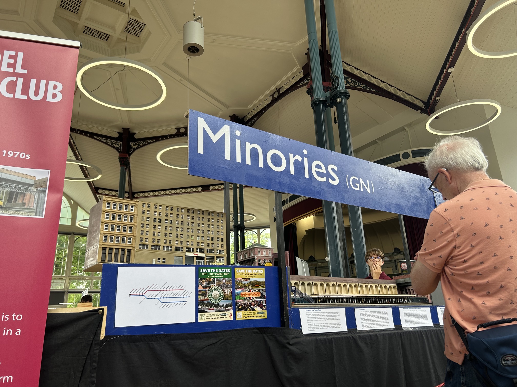
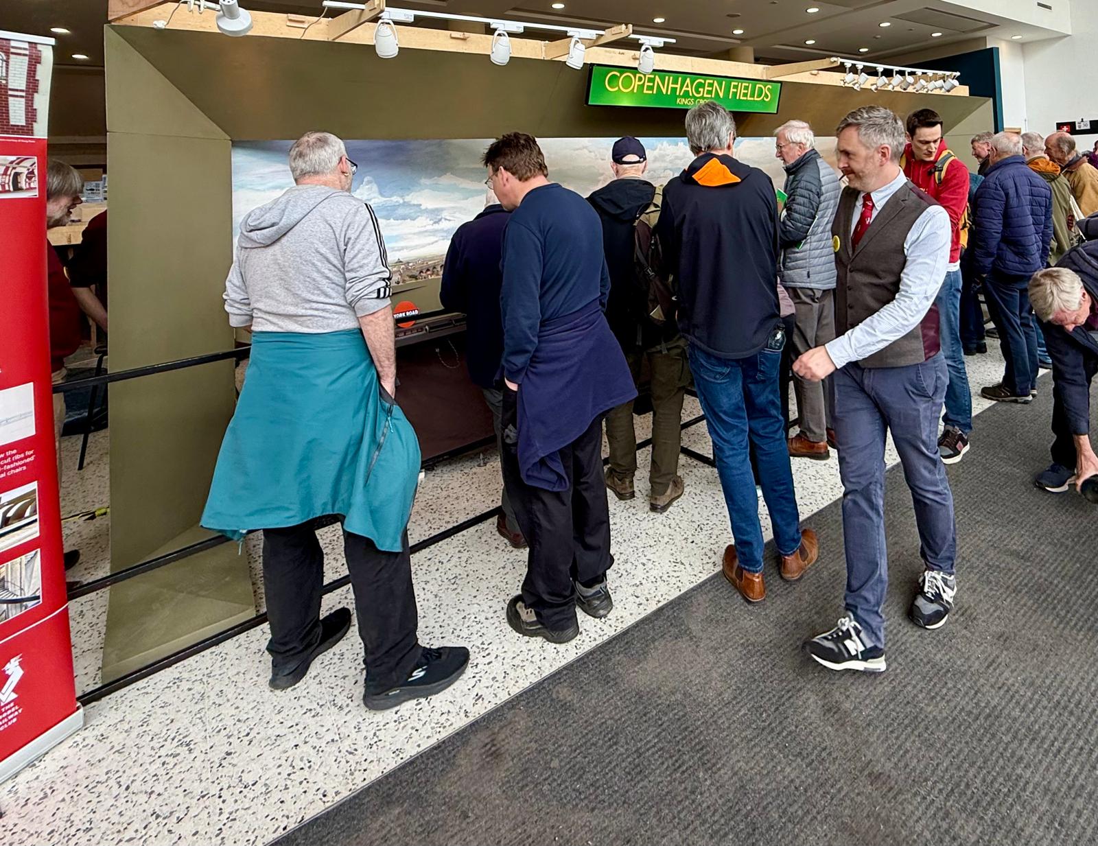
First Public Showing
At short notice, the layout had its first show at the London Festival of Railway Modelling at Alexandra Palace in March. I talked myself hoarse, gave out 300+ leaflets about it, got a lot of comments about my legs(!), mostly favourable and some good ideas were exchanged. It was great fun.
Suppliers (with the usual disclaimers)
Nuts, bolts, washers and screws and many other bits:
Apsley DIY, 38, London Road, Apsley, Hemel Hempstead, Herts. Tel: 01442-264793
Electrical bits:
The original suppliers have all ceased trading.
[*Perhaps – an interesting word when said slowly – expressing possibility with uncertainty: it may be, possibly, perchance, as may happen or be the case, as is possible, by any chance, peradventure, percase – from the Oxford English Dictionary.]
You may also like...

Thursday Track Nights
We are open on Thursday evenings from 7pm to 9pm at our Keen House clubrooms. Visitors are welcome, please come along and introduce yourself.
Address:
Keen House, 4 Calshot Street, London, N1 9DA
Become a member