Sarum Road – Part 5 – The Power Box
Michael Joseph
11th June 2020
4 minutes
You can go back to the beginning of this series and see the previous instalments here: Part 1, Part 2, Part 3
This was going to have been an article on the traverser but it started getting difficult and so whilst cogitating on how to build the thing, I decided on building the power box.
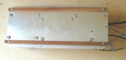
However, before the powerbox is discussed, here are a couple of photos of the underside of the two middle baseboards, electrically they are the most complicated:
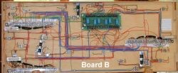
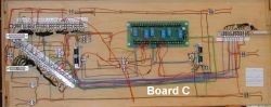
The excellent relay panels came from Trainlink Ltd and were reviewed in British Railway Modelling recently and in Railway Modeller last year. With hindsight, if I had made the boards at least 1.5″ deep, I could have used some of the excellent motor driven pointmotors such as Tortoise. Going for only 1″ deep has meant a lot of extra wiring.
The Power Box
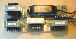
There are five(!) transformers in the unit:
- One unit,12v ac, for overhead lighting using halogen bulbs – this was part of a lighting kit and comes as a fairly awkwardly shaped lump.
- One unit, 24V ac for the capacitor discharge unit.
- Three units, each with dual 16V ac output for track power, perhaps lighting and to power the traverser.
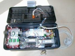
The transformers were to be mounted on an aluminium chassis and housed in a small plastic workbox from Homebase. After a long chat with Robin Almond (experienced in electrical assembly practices), I had a fair idea of the electrical requirements. We both felt that the job MUST be done professionally, not only would I feel happier doing it properly, but also one day there will be a difficult fire officer at an exhibition…
The basic guidelines were as follows:
- The chassis must be earthed and all its sub-members. To make this easier, Robin suggested fitting a ‘pylon’ to the chassis so which all earth leads could be clamped. I also used this idea on the sub chassis with the chocolate blocks to earth the secondary coils (see item 3).
- The transformers, even though bolted to the chassis still have to have a separate earth lead – yes, seriously, I couldn’t believe it either, but it is what the regulations say!
- The secondary coils must be protected by magnetic circuit breakers (MCB) – normal sort of protection,
- Mains cable to be fitted with a clamp to prevent it being pulled through the box. With hindsight, I should have fitted a ‘kettle’ type socket and lead. 5. Power to be externally switched, preferably with a neon light.
- Black on yellow warning notices on the outside – ‘Warning – 240V’ and ‘Disconnect before opening’ – these can be bought from trade outlets.
- Padlock on the box so that unauthorised or inadvertent entry is not made easy.
- And well ventilated!
Two wooden runners are used on the underside of the chassis and these are then separately screwed to the box. Complicated but it was done so that the screws did not have to be earthed as well! Phew!
The photos were taken during assembly – it looks complex but was really not difficult to put together. Everything was done in discrete steps, rather like putting a kit together. Once the chassis was cut, it and the transformers were put in their final positions in the box, positions roughly marked, then squared up neatly and drilled etc. The extra metal work was applied in stages and when complete the transformers were wired up and the chocolate blocks fitted. A fan (for a PC’s CPU) was fitted with grills for forced ventilation – these came from Maplin. The only thing missed was to sheath the soldered joints on the mains side of the transformers. Since the box is labelled and locked, the view was that it would pass muster. However, for personal satisfaction, I will do this once I have some suitable heat shrink. Finally, transformers and the main inputs and outputs were all labelled, cables were clamped with cable ties, etc, etc. Robin gave it his seal of approval which was very gratifying.
Bits etc. (with usual disclaimers)
Transformers from: Junction 20 Models, 51, High Street, Kings Langley, Herts. Tel: 01923-270247
Relay panels from: Trainlink Ltd 8, Mickley Lane Sheffield, S17 4HB. Tel: 0114-236-9200. email: Trainlink@btinternet.com
Fan and grills from: Maplin Electronics – www.maplin.co.uk
Part 6 is coming next week
You may also like...
Thursday Track Nights
We are open on Thursday evenings from 7pm to 9pm at our Keen House clubrooms. Visitors are welcome, please come along and introduce yourself.
Address:
Keen House, 4 Calshot Street, London, N1 9DA
Become a member