Sarum Road – Part 6 – Building the Traverser
Michael Joseph
18th June 2020
3 minutes
You can go back to the beginning of this series and see the previous instalments here: Part 1, Part 2, Part 3
It looks complicated but it is not. It was derived through trial and error with a number of attempts at a suitable drive system were attempted before one that worked was found.
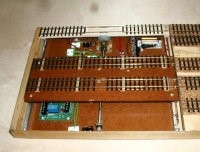
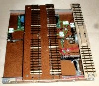
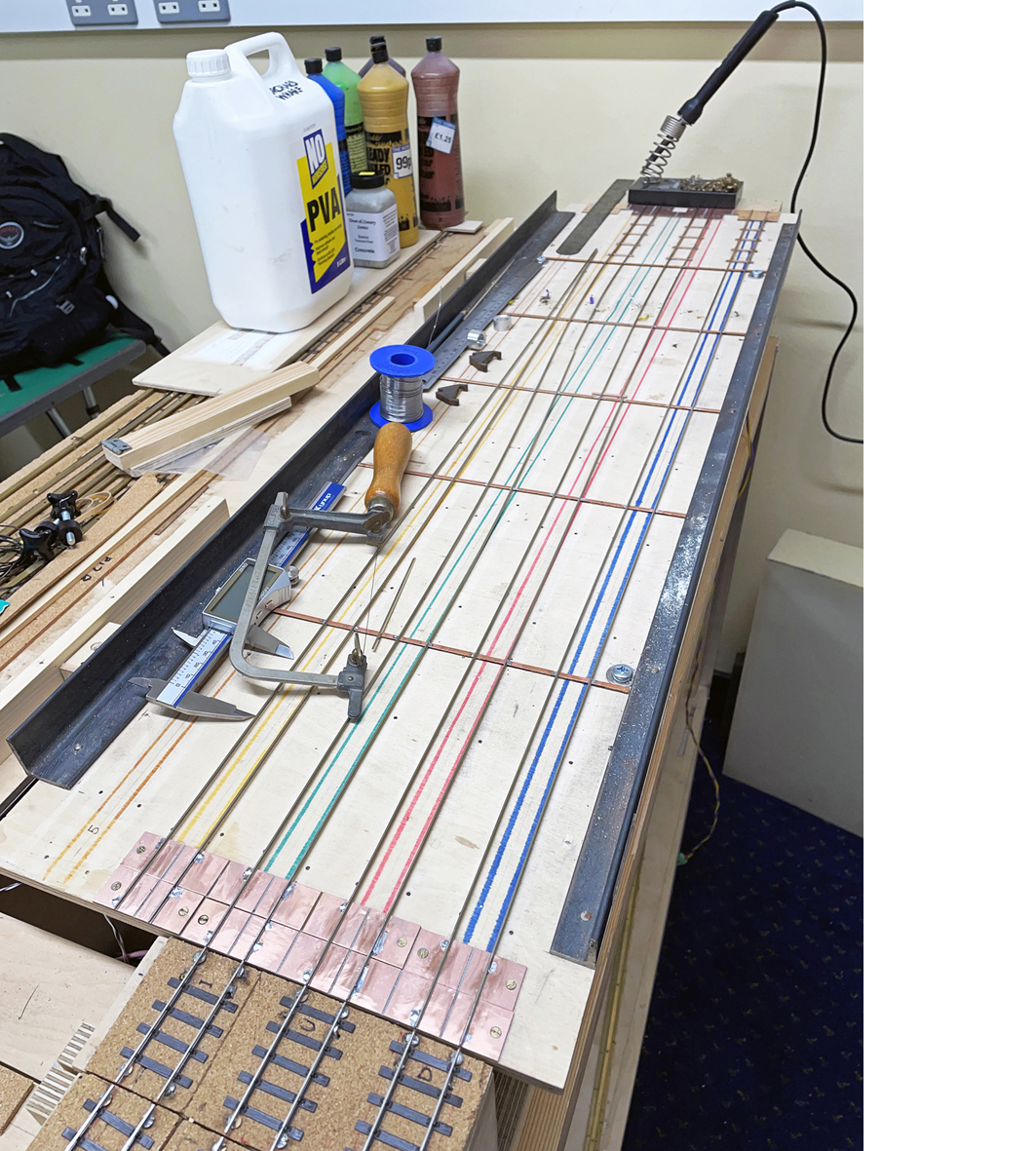
The complete traverser mounted in the baseboard
The whole traverser has been built to allow its easy removal for adjustment and testing and so has been made as a completely separate assembly
I used some MDF, (careful with the dust when you cut it – use a breathing mask), for the base and the traverser table. Four 25 x 3mm bolts were fixed at each corner and then on the tip of them was soldered some brass U-channel – this located on some aluminium angle so that it could slide. When building the drive, I started off with a motor and gearbox assembly from an educational site but found that the motor barely had enough power for the gearbox and certainly not enough to drive a traverser. It was only a small 4.5V motor and so I tried another from a similar source that was somewhat bigger with the same result. Frustration and the beginning of real worry. As luck would have it, I was speaking to John Jesson about something entirely unrelated and mentioned my problems. “I’ve got just the motor!” says he and so he had! I dummied up the drive as a direct coupling and there was loads and loads of power.
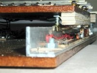
Motor mounting
The screw drive is a section of 4 mm studding – it is the second one fitted – the first had a slight curve in it – this one also has but it is now a lot less after checking on a piece of mirror glass. On the underside of the table is a bracket with two screws soldered and this drives the table. I originally had a fixed coupling – turned on an old Unimat SL lathe but found that the vibration was far too much and therefore cut I with a fret saw and used a piece of polythene tube to create a very crude flexi-coupling. (The clean holes in the polythene were cut with a standard paper hole punch!). The motor bracket was made from some brass angle I salvaged years ago from a scrap merchants..
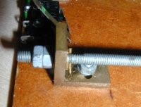
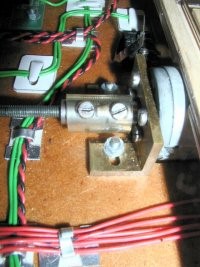
Fixed bracket
The other end of the screw has a fixed bracket with a bit of adjustment – the very fine taper pin is used in the clock trade. Two microswitches were fixed at each end to prevent over-running and, in conjunction with the relay board (Trainlink), swap the polarity of the power to the motor. At the moment, a set of fairly crude wiper system is used to get power to the relevant track on the table, but I hope to replace this in time with a properly set up system of photo cell sensors.
Bits etc (usual disclaimers)
Relay panels from: Trainlink Ltd 8, Mickley Lane Sheffield, S17 4HB. Tel: 0114-236-9200.
You may also like...
Thursday Track Nights
We are open on Thursday evenings from 7pm to 9pm at our Keen House clubrooms. Visitors are welcome, please come along and introduce yourself.
Address:
Keen House, 4 Calshot Street, London, N1 9DA
Become a member